What we know of the KC&S and AKO&M Tramway System.
There were two overrope tramways one from the bankhead of today’s Scenic Railway (the incline) to the “shoots” where the coal and shale was loaded into NSWGR trucks. The Shoots Tram. One from the bottom of the incline to the Glen Shale mine in the Megalong Valley. The Glen Tram. Also, a pony hauled tram from the Ruin Castle to the Junction. The Pony Tram.

The Tramway System: Red “The Shoots Tram” – Green “The Glen Tram” – Blue “The Pony Tram” – Yellow “The Incline” – Orange “The Glen Incline” – Sixmaps.
*****************
J B North’s admission to the Sydney Stock Exchange in 1874 has proven much more lucrative than his coal mining venture in Katoomba and resultant land sales. So he decided to get out of the coalmining business but retain an interest so he could continue to receive funds.
On 3rd February 1887 JBN set up the Katoomba Coal and Shale Company Limited, and it is recorded on the Title Deeds in 1887, JBN leased all his coal, shale and mineral interests connected with the mine to the Company, with substantial payments and royalties payable to him.
Jan 1885 JBN forms Katoomba Coal and Shale Co Ltd with himself as a Director and others.
Aug 1885 JBN Leases the seams, and existing equipment that he owns with operating rights to the KC&S Ltd.
Aug 1887 JBN Buys into or creates City Coal Co to distribute coal from Katoomba mines within Sydney.
Mar 1889 KC&S pays 12 ½% dividend to shareholders holding preferent shares.
Apr 1889 EGM held of KC&S
“That this meeting hereby gives the Directors the necessary powers to sell and absolutely dispose of the whole property of the Company, at not less than par, In such manner as they may think fit ; and hereby authorises the Directors to appoint by power of attorney, under the seal of the Company, an Attorney In London or elsewhere, with such powers as the Directors may think expedient, to act for the Company in the sale of the Company’s property.”
By order of the Board
- B. S. BUZACOTT, Secretary.
This is very interesting, as it is my reading of the Lease that JBN retained ownership of the land and the only “property” of KC&S was any equipment or installations that had been in place, which did include the aerial ropeway a pretty big asset!. i.e for “property” do NOT read “land”.
KC&S is running short of funds, the ropeway is costing a lot more than planned and is still not operational. A lot of shale is sitting “at grass” at Ruin Castle.
May 1889 Pedant Tramway operational.
Sep 1889 Failure to pay miners. KC&S short of funds. Shutdown until April 1890.
Oct 1889 EXGM of KC&S to increase capital to £90,000. [ Apparently not very successful, JBN had to mortgage more land to R H Reynolds to raise funds.]
Dec 1889 EXGM of KC&S to consider “the whole of the company’s property be sold…..”
Appoint Power of Attorney in London – [Looking for potential buyers there]
Feb 1890 Letter from JBN to Katoomba Times denying KC&S sold viz:
Katoomba times Sat 8th Feb 1890 to the editor of “THE KATOOMBA TIMES.”)
Sir. — You are continually making reference in your paper to the private matters of the Katoomba Coal and shale Company Limited, without first inquiring into the truth of your statement. In your issue of February 1st instant you say ” Katoomba Coal and Shale Mine has been sold to an English company for £30,000.” This is not true, and you have no right to make such a statement.
I must request that you report to, or advertise in the Herald, and in your next issue that the statement is not true, and apologise for having stated it. It is a fact that it is under offer in London for the sum of £80,000, and how you could think or making the statement that the company’s property was sold for £30, 000 I am at loss to conceive. I trust that I shall not again have to complain, and that you will not interfere with the company’s private affairs, as, if you do, I shall hand the whole matter over to the company’ solicitor.— Yours, &c:.,
- J. B. NORTH.
Managing Director K.C. and S. Co., Ltd. The par. referring to the mine being sold for £30,000 appeared in the S.M. Herald, with which we have nothing to do. Mr. North might ask the
Herald to apologise. — Kb. K.T.
Jun 1890 EXGM of AKO&M to “ACQUIRE OR LEASE CERTAIN PROPERTIES”. [ AKO&M had to dissolve the company and restart it under the same name to be able to do this. I’m guessing that their Constitution did not allow them to lease other properties]
Jul 1890 JBN elected as alderman of Council.
Jul 1890 EGM of KC&S held “confirming sale of Company’s property to L. P. Bain and London Chartered Bank”.
Lewis P Bain was a stock and sharebroker, living around the corner from JBN in Ashfield.
NOTE: This is the property of KC&S not land
NOTE: I assume that this was an intermediary way of handling the financing of the deal between AKO&M KC&S and JBN. “Bridging Finance”
Aug 1891 Lease of land owned by JBN AND “rights liberties and licenses” of KC&S to AKO&M signed.
Mar 1892 JBN liquidates KC&S.
Aug 1892 City Coal closed down.
In 1889 he mortgaged his house in Katoomba, Essendene, to Thomas Cooke and moved back to Sydney with his wife, Clarissa and 7 children to live in Ashfield.
In May of 1889 the Bleichert Ropeway to the Ruined Castle shale mine is reported to be operating but by August labour troubles are evident as a liquidity problem of KC&S has resulted in the miners not being paid.
In September of 1889 an Extraordinary General Meeting of KC&S was called to increase the capital by £20,000 to £90,000. This capital raising was not a big success, and JBN decided to lease the whole operation.
In January of 1890 JBN has decided to get out of the Katoomba Coal Mine business. The Company that he created to carry on the mining business “Katoomba Coal and Shale Company Ltd” [KC&S] is struggling as the Bleichert Ropeway is proving to be a maintenance nightmare.
Further labour trouble in March and April of 1890 resulted in a swathe of new operating rules for the colliery, and miners went back to work.
Fortunately for JBN, Australian Kerosene oil and Mineral Co Ltd [AKO&M] were looking for investment opportunities outside of Joadja, as their shale supplies were being mined out. Robert Vernon Saddington was the man running AKO&M.
Looking at the land records it cannot be a coincidence that Pors XIV and XV Parish of Megalong County of Cook were purchased by one Charles Paubury/Parbury , [Director of the Union Bank of Australia] in March of 1890 and that KC&S appointed Powers of Attorney in Nov 1889 to sell the mining operation. The problem with AKO&M having to shut down the business and start it up again under the same name may have necessitated Parbury holding onto the property until AKO&M could get their ducks in a row, and finally buy the properties from him in November 1891.
A series of Emergency General Meetings were held to enable all this to happen, along with wild rumours of JBN selling out. The mines were closed down while arrangements were made, and slowly resumed by April 1890.
The crucial parcels of land necessary to open the Mort’s Glen shale mine were Por XIV and XV Parish of Megalong County of Cook. [Vol-Fol 142-128 and 267-87 – c/o John Fox] On 3RD March 1890 Pors XIV an IV were transferred to Charles Paubury, Merchant of Sydney then on 16th November 1891, from Charles Parbury to AKO&M Limited. [Note the change in spelling of his name, Parbury is the Director of UBoA, Paubury results in a blank search].
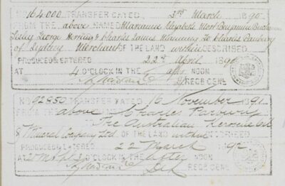
Charles Parbury also bought a 5-acre part of Mort’s Por 10 on 3/3/1890 >Vol-Por 968-158 > 972-116 {residue} fronting GWH but not the Adjoining Por 11 which contained a small part of the Nellies Glen access track. This 5-acre lot was then transferred to AKO&M on 16th Nov 1891. This block adjoins JBN’s Por 65 to the West. Maybe Saddington was going to build a grand house there!?! Today this is DP 713158 a steeply sloping bushland block. North had owned Por 210 since 1884 so he had the Nellies Glen access covered.

Originally bought “at upset price” by Thomas Sutcliff Mort on 14th October 1868 for £320 Sterling after Campbell Mitchell discovered the outcrop of Kerosene Shale there. Then on 9th March 1892 a transfer from AKO&M Ltd to AKO&M Ltd. A strange one, I think something to do with a change to the company’s Articles permitting AKO&M to lease KC&S Ltd. Lands were very slow to update, this transfer not entered until 1896!
The other crucial piece of land to open up the Mort’s Glen mines was the tramway lease from JBN’s property to Por XIV. This didn’t appear in the Govt Gazette until 29th September 1891.
The Western boundary of JBN’s Por 74 was the Mt Rennie Tunnel Western Portal, so the tramway went through JBN’s Por 87, then Crown Land, until the Northern boundary of Charles Smith’s Por 85 then through Susan Edwards Por 84 and 83, until hitting the Northern boundary of Por XIV.
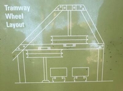
My sketch of the arrangement of the reused counterwheels.

c/o UBMBC Inc John Cooper.
Many things were happening in 1890 as AKO&M prepared to take over. Here is a Trove snapshot:
August 1890 JBN transfers the lease that he gave KC&S Co Ltd to AKO&M then in 1892 liquidates KC&S.
August 1890, AKO&M company representatives arrive to take over Katoomba Colliery.
21 Jan 1891: The surveyors have almost completed their survey of the route for
the double line of railroad from the mouth of the coalmine to the shale. It is understood
that next week the work of clearing the track will be commenced. Tenders were called 11th July 1891.
The Bleichert Ropeway was operating but giving a lot of trouble. In light of this, Mr Duff was started on constructing a pony tramway from the mine to the proposed tramway.
Jan 1892 the Narrow Neck Tunnel was pierced.
5th Feb 1892, Mr Lewis Duff has nearly completed the tramway to the mines. AKO&M are expecting to bring their first load of “the new shale” next week. – So, they have got the tramway to Morts Glen operating. – No, an ambitious report.
4th March 1892 “Mr L Duff sen. has the construction of a tramway to the old shale mine near Mount Solitary”.
4th Mar 1892: AKO&M are loading a vessel with Katoomba Shale, from The Glen or Ruined Castle??.
On 23rd April 1892 the track rope of the Bleichert ropeway broke at Tower 7 on the edge of the cliff.
This event precipitated the commissioning of the Glen Tramway as it was always planned to use the Bleichert Ropeway drive to operate the Glen Tramway. The ropeway haulage rope was recovered and as much equipment as possible salvaged especially the lead filled tension weights from the tension pit. They even tried to recover the last length of outbound track rope North of the Tension Pit. They failed, and it is still draped over the rock platform below Tower 10, which was as far as they got it.
29th April 1892 “Mr Duffs tramway is progressing favourably”.
13th May 1892 The second new tramway is progressing favorably.
12th August 1892. AKO&M have decommissioned the hauling engine at Katoomba South (tramway) and all hauling will be done by the engine at the shoots. [Northern end of the Tramway, which JBN installed in June 1888. The original engine for the Shoots Tramway was installed in 1882]
This proved a bad decision as 7 months later they moved the shoots engine to Katoomba South. A large section of the concrete footing for the Boiler/clip pulley broke off and I also suspect that water supply for the boiler was also a problem. The initial idea was that with the increased haulage that the tramway would have to do, carrying the additional shale brought over by the ropeway, that more power was needed, hence a clip pulley and drive was installed at the top end of the tramway. This was not the case.
The AKO&M plan was always to use the Bleichert drive to power The Glen Tramway once the pony tramway was completed. When the ropeway broke, zero shale was coming out, so there was a lot of pressure to complete both tramways.
AKO&M must have always planned to use the return wheel from the Bleichert ropeway, which was at the Ruined Castle end, at the Glen end of their tramway, with a last minute transfer, once the ropeway was shut down. They could have had the ropes run out with a temporary return sheave at the far end, so that they could transport the return sheave on the tramway, but Mr Duff’s pony tramway had to be finished first!
It would have fitted through the Mt Rennie Tunnel, as the shaft could be removed.
I can only conclude that the two counter wheels [now outside the Megalong Tea Rooms on display] were never used for the Katoomba Ropeway installation and were available for installation at the bend in the Glen tramway. As their shafts could not be removed, being held on the shaft with shrink rings, it is unlikely that they would have fitted through the Mt Rennie Tunnel, and the tunnel through the Katoomba Coal Mine, and the incline tunnel, so they would have had to be transported by bullock dray, via Blackheath Glen Road. Quiet a trip. I suspect that this is where one of the wheels sustained a huge piece being cracked out of the rim and having to be riveted back together. [See the separate paper on these wheels].
Digging the tunnels:
Four tunnels were needed. One through the workings of the Katoomba coal Mine, Tunnel (dubbed the “Daylight” tunnel as it was straight and daylight could be seen from one end to the other, and its portal was not far from the “Daylight Heading” of the mine which gave access to the ventilation furnace tunnel nearby.), two short ones through a ridge just West of the western portal of the Coal Mine and the Mt Rennie Tunnel through Narrow Neck.
There was a ventilation adit for the Katoomba Coal Mine near the Western Portal (under what is today’s Landslide) so access to both ends of the Daylight Tunnel was available, so it could be worked on from both ends, as was usual practice for boring tunnels. Tracks would have been laid as the tunnels progressed to remove spoil and of course they didn’t throw the coal away! As it was going to be a tramway, twin tracks would have been laid. In July of 1891 AKO&M called for tenders for clearing and forming 2 miles of tramway. This had to be done before work on the Mt Rennie Tunnel could be started, as there was no access to the Eastern Portal.
It is pure conjecture on my part, but AKO&M had been using a rope driven air compressor to trial bore an adit in the lower seam, once the Bleichert drive was operational, but the ropeway wasn’t. The drive was operational in Nov 1888 but didn’t start hauling shale until May of 1889. The ropes can clearly be seen in Kerry’s photo. For the Glen Shale tunnels it would have been possible to follow the tunneling team with a rope driven compressor as they progressed eventually to the Mt Rennie tunnel, extending the ropes as needed by splicing in extra length.
The western portal of the Mt Rennie Tunnel would have been a very difficult one to dig. It was steeply uphill, so at least the spoil would be easy to get rid of, but through rock, not following the coal seam as the eastern portal could do, and no compressed air to help. As was the case with the Eastern portal, water just drained out, a great advantage!
Explosives had to be stored in a safe place while tunneling was taking place. Usually, a brick or stone store was constructed near the tunnel portals well away from any campfire sparks. These were always very solid constructions and should have survived. None have yet been found, except for the one at the Bankhead of the main incline.
Wire rope:
The tramway length is 4.5 kM. The rope has to be double that length plus distance around deflection sheaves, tensioning sheaves, and drive sheaves, total rope length is 5.1 kM, therefore 10.2 kM of ¾” 6/19 rope is needed. At 1.52 kg/M that is a total of 15,504 kg.
15 tonnes of wire rope cannot be handled on a single reel in 1892. Limiting factors are the 5 Ton crane at Katoomba Station and whatever tripod and block and tackle are available to unload the bullock dray at the top of the incline. Then the capacity of the incline to lower the reel to the bottom. The incline was designed to operate five ½ ton coal skips, dead weight 3 tons. The incline was double reversing so it was lifting 3 tons counter weighted by ½ ton of empty skips, so dead lift was 2 ½ tons.
The brake on the steam winder was designed to hold a full rake of skips on rope break on the empty side, so it had the capacity to lower the full three tons down the incline, and to make it easier a full load of skips on the up side would have been used to “lighten the load”.
So, 3 tons is the maximum that could have been lowered into the valley. 3 tons of ¾” 6/19 rope is 2,000 metres long. So, 5 reels of rope are needed. The reel, mounted on or tied down to a special skip, would also have to fit through the incline tunnel.
A shipping reel for 2,000 metres of ¾” wire rope would be 1M wide, 1.4M diameter. So, it could be laid on its side to go down the incline no problem.
There are two ways to install ropes like this. Mount the reel and pull the tail out or put the reel on a skip and pull it along, with the tail tied to something, reeling out as you go.
Whichever way it was done, if they used the rope driven compressor on the Western heading, it would have to be in fairly large steps, driven by how much pipe or hose that you could obtain.
The Eastern heading of the Daylight Tunnel would have to be hand driven, unless air could be piped through the workings to outside and back in again. This would be limited by friction losses in the pipe.

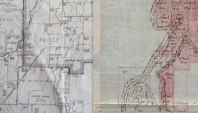
The red line is the Daylight Tunnel. Just where it emerges from the workings top left is penciled “Daylight Heading” and is where a ventilation furnace was located. So, access to the Eastern portal was much easier through the workings rather than around the outside and would have been regularly used to man the ventilation furnace. Source: Dept of Mines.
Lowering the reels down the Western talus slope would have been tricky, maybe they stopped at the downcast in the Mt Rennie tunnel and pulled the tail downhill.
There are scrape marks on the upper lip of the turnwheels, indicating that a rope was pulled across the top of the wheels, possibly a bullock powered tractor dragging the ropes in a straight line down from the tunnel before re-routing around the turnwheel and on to the terminus.
Five reels of rope need 5 splices, to get an endless rope for tramway haulage, keeping in mind the use of the cable powered compressor, splicing as needed.
Skips:
By 1883, JBN’s original system for material handling had been “modernised”. The lower tippler and gravity incline outside the coal adit had been done away with, and a new platform built on the contour of the coal seam. This meant that a skip could journey all the way from the coal face to the loader above the GWR siding via the incline and the Tramway. Pony haulage was used from the bottom of the incline to the coal face.
Photographs (of which we only have two) indicate that round bottom skips were being used by AKO&M on the pony Tramway from the Ruined Castle. This means that side tipping was being used to unload the skips at The Shoots. This idea is also supported by finding discarded wheel sets with captive “U” bolts, to restrain the axles when the skip is tipped sideways. This method is more efficient as the skips do not have to be hand reversed into and out of the tippler, just pushed in, locked down, tipped, unlocked and pushed through. With a skip arriving every minute, there was not any time to be wasted.
At “The Glen” an argument has been put forward that the Gravity incline down from the shale contour to the terminus of the Tramway enabled the skips to travel from shale face to tippler. We are mounting an expedition to check out the transition of the incline to the tramway to see if this was possible.
Michael Keats mentions in his UBMBC paper of 19th April 2021, page 13, of the existence of a skip storage cutting at the Glen. I have also noted it. This had to be, as the self-acting incline had to store skips until an up trip was ready, plus as you can see below, any incident delaying traffic in the system will quickly generate a surplus of skips, which have to be held somewhere.
Traffic Control:
Both empty and full skips have to be transferred from the pony Tramway to the Glen overrope tramway at “The Junction”. We have one photo taken just East of the junction showing an empty skip approaching (we think) on the Southern track and loaded skips in the distance proceeding towards the main incline.

The system operated clockwise, as opposed to the ropeway which was anticlockwise. The approaching skip only has one rope grip on this side. This means that it is intended for Ruin castle track, because if it had to go down the Incline on the Western side of Narrow Neck it would also have had one at the back. Unfortunately, the departing skip on the left is so far away that we cannot see either if it is loaded or has one or two grips.
The “turnoff” for the Ruin Castle track is just behind the photographer to his right.
This trestle was across the headwaters of Cascade Creek.
The cliff face in the background was the one that fell in the landslide of 1931.
Working the traffic on the Junction wasn’t for the faint hearted. As this empty skip approached (at 1 M/sec) the ”gripman” walked alongside the skip and released the grip by twisting it with a sprag, then the skip was switched onto the Ruin Castle line with manually operated points. Once past the points had to be reset to “straight ahead”.
The grips were updated as time went on, initially they were just a snaffle chain, which saw the end of many a finger, which eventually became fancy auto release ones. This one appears to be a “C” clip which jammed onto the rope and had to be twisted to release using a short length of wood as a lever. This same piece of wood known as a “sprag” was used to jam between the spokes of the skip wheels to brake and stop them moving.
To insert a loaded skip onto the tramway, you waited until a space came along, then the “empties” rope had to be lifted so that the incoming skip could pass under it. It could be done manually if a man held his sprag under the outbound haul rope to lift it high enough to enable the skip to be pushed under the rope while it ran across the sprag, but it more likely had a small roller mounted on a swing arm that could lift the rope. Then the loaded (heavy) skip was pushed under this rope across the diamond crossing in the track. The lever-man then dropped the rope and lifted the other rope so that the skip could roll under that one passing through the trailing spring points to gain access to that track. Drop the rope onto the top of the skip to allow it to run on the wear timbers there. Then walk around to the front of the skip carrying the clip and chain, hook the ring of the chain over the hook on the front of the skip, then put the grip over the running rope. NEXT GET OUT OF THE WAY! Let the grip go and the rope will pull it and as it gets tighter it grips the rope and the skip instantly accelerates to 1 M/sec. A second grip on the back end may also have been fitted.
Working traffic around the turn wheels in the Megalong Valley was also a job for real men. Every skip, coming and going, had to be disconnected from the rope as it approached, allowed to run around under the wheels, then re-gripped on the departing side. Out here, both ends of the skip had to be chained and gripped, as the tramway went both up and down hill on its way to the terminal.
There are quite a few rope marks one the shaft of the inbound wheel, where the rope has escaped the groove of the sheave and smacked up against the shaft. Not a good place to be, it could cut you in half quite easily. There are no newspaper reports of such an event happening, so we assume not ?!?!?
Traffic:
The Glen tramway was 9 km long, out, and back. Skip separation was 60 Metres, running at 1 M/sec, so a skip trundled by in each direction every 60 seconds. 9kM/60M = 150 skips. Half a ton of shale per skip, 30 tons an hour, 240 tons in an 8-hour day.
Ruin Castle line:
A rake of pony hauled skips consisted of 5 skips, and every second skip on the Tramway was for the Ruin castle. So, these would assemble every 10 minutes. This necessitates a passing loop in the distance covered by a rake every 10 minutes because there has to be the same number of fulls inserted into the tramway coming from the mine. If we assume that 1 M/sec is reasonable for the pony haulage, to avoid derailing the skips on the rough rails, that distance would be 600M. The pony tramway was 3.6 km long so it would need 5 passing loops and 35 minutes for the journey.
At the mine end there was a “stable” at the bottom of a gently sloping 30M ramp below the track level, where the ponies were fed, watered, and rested. A 2” pipe supplied the water to the stable taking the drainage water from the mine. A large pool at the mouth of the adit held water for the ponies as well. At the Tramway end, we think a small dam in Cascade Creek high above the junction was used for watering the ponies.
The Glen Shale mine:
The Glen Tramway was fed by a self-acting incline from the mine level. Approx. 200M long. It probably handled 5 skip rakes, and would easily move them in 10 minutes, as the skips would be arriving and departing every 2 minutes, leaving a gap for the Ruin Castle skips to be inserted.

The Glen Shale mine.
This drawing is at mine closure Nov. 1st 1897. The cross hatched areas are where the roof has collapsed.
The Glen Incline was halfway between the #6 adit and the #7 adit heading due North. We don’t think that ponies were used on the seam level or at the Glen at all, all skip movements were manually pushed.

This is John Cooper’s profile of the Western Section of the Glen Tramway. A net rise of 70 metres in 3 km 2.3/100.
There was a further rise to the downturn inside the Mt Rennie Tunnel which was the highest point in the Glen Tram.
We are proposing to do a Garmin profile to get a more accurate profile.
Main Incline: (Today’s Scenic Railway)
It was (and is) 430 M long, so it had to fit in with the Glen tramway delivering and taking 5 skips in 5 minutes, plus the number of skips coming out of the coal mine. It was a “twin reversible”, skips moving alternately up and down adjacent tracks, fulls up, empties down.
1892 coal production was 22,462 tons. 52 weeks 6 days a week 9-hour days. Gives 72 tons a day or 14 – 5 skip trips a day. Way below the theoretical maximum.
Cycle time, allowing dwell time of 1 minute to fit four chains between the skips, and hook the haulage rope to the back one, say a run time of 4 minutes, gives a speed of 1.79 M/sec, readily achievable.
North’s Tramway from the Bankhead to the Shoots:
It was Initially designed to match the capacity of the incline, which had a 500M length, 2M/sec travel time of 4 minutes 10 seconds plus connect and assemble time, say cycle time of 6 minutes. Tramway capacity at 60M spacing 1M/sec, 5 skips in 5 minutes, so the tramway had spare capacity.
The first main change was to shorten the incline by bringing the platform up to the seam contour and eliminating the tipping/loading at the bottom of the incline. Incline was now 430M bringing the cycle time down to 4 min 34 sec, reducing the cycle time to 5 minutes, now matching the tramway.
Now we introduce the shale skips into the equation, coming from being loaded from the Bleichert Ropeway! It also was producing a skip every minute and requiring a fresh empty every minute.
The initial plan 1888 was to install a clip pulley at the Shoots end of the Tramway to replace the idler sheave there and provide extra power to lift the extra number of loaded skips up the hill. The skip frequency would have to be doubled to move all the coal and shale, so shortening the distance between skips to 30M was the plan. They couldn’t run the tramway much faster mainly because of the limitations imposed by the suspension bridge across the creek between Stuarts Rd and Wellington Rd.
Weighbridges:
An additional improvement in shortening the incline was to bring the weighbridge from the bottom of the incline to the contour of the coalmine. This ultimately captured all the output from three mines, 1 of coal and 2 of shale, with numbered leather or brass tags hooked on a nail on the outside of the skip.

This early photo of the bottom of the incline shows the weighbridge house. The black hole just to the right of the line of skips is the weighbridge box. The last loaded skip on the left is being weighed. There was a pipe from the top of the shoot into the hut to slide the miner’s token down to the weighman, for his weigh book. This is how the miners were paid, by the coal weights recorded against their names/numbers.
There are two types of skips being used, round bottomed iron ones and square timber ones. The “tare” or weight of the empty skip had to be subtracted from the total. This could have been done with a standard weight for the two types of skips, or the weighbridge could have had a counterweight feature that used an empty skip to balance a full one, but of course it had to be the same type of skip.

The ”new” weighbridge was in front of the white shed in this photograph.
When the ropeway was operating, the buckets were weighed as they were unloaded. I found a ½ CWT lead filled weight buried there, and a handle for lifting it on and off the weighbridge. I surmise that a section of the transfer rail could be unlocked to suspend the bucket and carrier and weigh the shale within. There had to be some miner identification if they were being paid by this method which seems unlikely, as the shale was loaded into the buckets from skips at the mine end and carrying the tags through this operation is impractical. So, I am open minded on this one.

The GWR also had a weighbridge on their siding to be able to charge the mine for carting their coal and shale. 3d a ton mile. You can see the weighbridge in the drawing in the “At the Shoots” section.
Starting and Stopping:
In the photo above of the Junction, two telephone wires can be seen on the right-hand side. These went all the way to the winder driver’s shed up at the top of the ropeway, and the Shoots Tramway driver and probably rang a bell when connected together. A telephone could also be connected across the wires. A code to indicate that all of the stations were ready and manned would be sent, and the drivers could start the drives.
1: top of Shoots tram
2: bottom of Shoots tram/top of incline
3: Bottom of incline/pony or hand transfer to Glen tram
4: Hook-on /Hook-off to Glen Tram – coal skips into & out of Coal Mine.
5: Ruin Castle turnout
6: Angle wheels Glen Tram
7: Bottom of Glen incline/ end of Glen Tram
8: Top of Glen Incline
The two tramway drivers would also have to have communication, so that if there was a stoppage on one, the other could be stopped to prevent a backlog of skips. As they were 50 M apart a simple clapper bell would have sufficed.
The Shoots tram was 2.2 km long so 4.4 km of ¾” wire rope 1.52 kg/M=6.6 tonnes plus rope to the tensioning weights and around the drive wheels, say 7 tonnes. Skip every 60 metres = (4400/60) =74. Total skip weights of empty, 37×200 kg=7.4 tonnes, and full, 37x700kg=26 tonnes. Total 33 tonnes. With a lift of 99 M in 2111 M at 1 M/s in a time of 35 minutes, with 35×200 kg unbalanced load plus friction, lifting power is less than 1 HP or 750 Watts. So obviously the clip pulley was to assist in starting, and when the concrete footing for the clip pulley cracked a large piece off the corner, where the thrust was transferred to the original turnwheel footing, it was a no brainer to move it to the bottom.
On the Glen tram, 15 tons of haul rope plus 75 loaded skips and 75 empty skips, total of 67 tons, (more than a loaded B Double) takes quite a bit of getting moving. The Bleichert engine was quoted at 80 HP.
Calculations from Craddock’s wire rope manual of 1922, show 60 HP is necessary for the drive.
The Bleichert drive sheave had 6 large grooves, oversized to accommodate the spiders inserted into the ropeway rope, very similar to the grooves in the counterwheels, so it would have been possible to use it as a surge wheel, and put two or three turns around one groove to get sufficient friction to drive such a big load. As the Gladstone Counter Wheels were being used for the “big bend” they could not be used as counterwheels as was the original design.

The two Counter Wheels on display outside the Megalong Tea Rooms.
The Bleichert turnwheel from the Ruin Castle end of the ropeway reused at the Western end of the AKO&M Tramway below the Glen Shale Mine.

Photo Philip Pells.

The round bottom skip is second in line. As the skips are empty, and the ground slope is from Left to Right, we assume that this rake of skips is going towards the mine. (And the passengers are on their way back from church).
This photo shows a passing loop, where one rake waited for a loaded rake coming the other way. The points in the foreground are spring loaded so that the leaving rake just pushes its way through, and an arriving one is directed to the left hand of the loop.
There may have been a “staff” system which had to be carried to proceed into a section, to avoid head on problems. There were possibly five of these passing loops between the mine and the junction.
Track switching:
Facing or trailing are two types of railway turnouts (or ‘points’ in the UK and Australia) in respect to whether they are divergent or convergent. When a skip traverses a turnout in a facing direction, it may diverge onto either of the two routes. When traveled in a trailing direction, the two routes converge onto each other. The rake in the picture above is trailing.
Points can be of three types. Switched, sprung or lazy.
Switched points have to have the blades manually moved with a lever, then held in place, usually by a counterweight on the lever.
Spring points, as in the picture above, have a vertical plate against which the outer rim of the wheel pushes so that the flanges of the wheels can push the pair of blades across and allow entry to the track. As the wheels pass, the spring returns the blades to their original position.
Lazy points are similar to spring points without the spring, the blades stay in the position left by the last passing skip. So that a facing rake will switch onto the same track.

Here is my explanation for your comment.
A similar set would have to exist at the bottom of the Glen incline to deal with the alternate sides of empties and fulls being switched to inbound and outbound tracks on the tramway. There the opposite is happening; the empties are going up and loaded coming down so the switching arrangement would have been reversed. That is assuming that there was not enough available flat ground to accommodate the point set, where both sets could be lazy points and would work well. The disadvantage then would be having to manually push the skips through the point set.
Another set was at the top of the main incline, to deal with the full skips alternately arriving on Right and Left tracks and delivering empties to the same tracks for being sent to the bottom. This set was on the flat just over the top of the incline, where the Shoots Tram was delivering empties on the western side and taking fulls away on the Eastern side. On the Tram side of the point set was a long enough piece of track to hold the five skips being delivered up the incline, also a similar piece to hold the empties being delivered from the Shoots Tram.
An additional complication while the Bleichert ropeway was operating, was that skips were also arriving and departing from the ropeway terminus. Every second empty skip had to be turned out to the ropeway siding, and fulls arriving from the ropeway siding had to be pushed through the diamond crossing and put in the queue of waiting skips coming up the incline from the coal mine. A manually operated facing point would be needed for turning out the empties, and a trailing spring point for the fulls.
A safety block was just on the incline side of the point set to stop runaways going down the incline and catch point about 50’ down the incline on both sides to derail the empties if a rake got past the safety block. A three-link chain was used to hold the 5 skips together, hooked around the heavy hook on each end of each skip.

The three-link chain used to hook the skips together. It has to be three links so that each end link is horizontal for the hook, with the third link vertical in the middle.
Points Operation at the top of the incline (The Bankhead)
As a full rake approached (say) on the Eastern side its lazy point would be pushed over to allow it to pass. Now on the flat, the full weight of the loaded skip could operate the lazy point. The tramway side point would be switched to bring the full skips to the full or Eastern side of the Shoots Tram.
Once all 5 skips were past, the tramway side point would be switched to allow the accumulated empties to be pushed all the way past the lazy point to the East side incline track and allowed to roll up against the safety stop. The chain links were probably fitted as the empties arrived to save time.
The next event is a rake of fulls arriving on the Western incline track. They push the lazy points over and the Shoots Tram side points have to be switched to pass them to the East side of the Shoots Tram. These points then have to be switched to allow the empties to be pushed to the West incline track across the lazy points just set by the full rake and down onto the safety stop.
Once the fulls were hauled up onto the point set past the safety block, the haul rope was unhitched from the hook on the back of the top skip and the skips pushed up against a further safety block, which protected the Shoots Tram, as the first part of the track was downhill. While the banksman commenced hitching the skips to the Shoots Tram rope, at 60 yard intervals, the ropeman took the tail of the haul rope and as the driver let slack out he pulled it to the back of the waiting rake up against the lower safety stop. When hooked on, he signals the winder driver, maybe with a clapper, as he is out of sight of him, and the driver winds in until he has the weight of the rake then stops. The ropeman disables the safety block. The driver is now awaiting a signal from the bottom points that their rake is ready, initially with a clapper, later replaced with an electric bell, in order to commence lowering them to the bottom while pulling a new fulls rake to the top.
Safety Blocks

This photo taken to publicise the Three Sisters, with the Katoomba Coal Mine incline in the foreground, shows the catch points in the lower RH corner made from timber. That had an interlock – a timber block – that prevented the catch from being operated if the haul rope was in place. i.e., it could only be used if the rake was NOT down the incline.
Catch points are designed to derail a runaway skip.
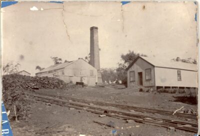
This photo shows the Shoots Tramway with the winder house in the background. The building held two boilers, the endless winder for the tramway and under the lean-to roof the incline winder. The gable roof in the far-left background was probably the blacksmiths shop. As you can see, the initial run of the Shoots Tramway was downhill hence the need for safety blocks at the top of the hill to the left. The huge pile of material on the left is Oil Shale.
The English mining books refer to a “bull” which is a large timber which the uphill skips push past, which then rises back up again to catch a runaway skip. A “block” is a set of timbers which can be raised between the rails for downhill bound skips to run up against until the rope is attached.
Points at the Junction:
The Westbound approaching empties on the tramway are running into a facing point, so they have to be switched to divert to go to Ruin Castle or left straight to go to the Glen.
The fulls from Ruin Castle have to cross the outbound track on a diamond, then run through a trailing point to join the inbound side, which could be a spring point to accept the next inbound full from the Glen.

This diagram shows how the whole cable drawn system was laid out. I have the direction of the Shoots tramway and the Ruin Castle ropeway wrong, and the Glen Tram did not change sides at the angle turnwheels.
At the Shoots.
We don’t have much information on how this worked apart from two GWR (Great Western Railway) drawings that are not very helpful.
We do know that there was a facility to pass unwanted shale and coal from the Tramway over the GWR tracks and store it on the steep slope to the East. At the bottom there was a “Recovery Road”, a hopper or bin built over the creek, that could load a tip dray, to be hauled back up to the top via Gundar Street.
There also had to be a facility to store shale and coal separately for loading into NSWGR trucks.
The coal was also separated into nuts, smalls and large with steel screens. The shale wasn’t sorted by size, only quality. This was probably done at the mine adit as the skips came to the surface. There are mentions of large stacks of “seconds” outside the mines.
These NSWGR drawings do show two shoots, one covering all three tracks and one emptying onto the first track. I surmise that the short one was for the recovery product, and the long one was long enough to push surplus product over the end and down the hill.

The Shoots end of the Tramway has been severely damaged by a landslip, so it is difficult to tell what has been there, but we do know what HAD to be there:
A turnwheel for the haul rope that had to be 5’ working diameter. The centre lines of each track were 5’ apart. The concrete footing for this and the later clip pulley and boiler/engine have survived.
The turnwheel had to be 3’ or 4’ above the track level of the unload area to lift the rope away from the top of the skips.
There was probably a “kip” or hump on the track at it topped the incline the same height as the turnwheel to provide an anti-rollback and to keep the haul rope level across the area making it easier to unclip the skips.
A facing point which had to be switched to direct the skips out onto the Shoot for unloading, coupled with a spring trailing point for bringing it back.
A side tippler above the closest siding and a sloping set of screens to size the coal into the three bins, nuts, smalls and large. No screen on the “large” bin everything else went in there. The track extended out past the last bin where there was a tippler to feed the recovery slope when the bins were full.
The recovery facility was very important. As detailed in this paper, it was a long and complex system, difficult to stop if anything went wrong, so the ability to deal with “unwanted” product at the delivery end was very necessary.
If the skip contained shale, it was pushed past the first point, through the trailing spring point and on to the shale tippler. With no need to size, it was probably a simple side tippler discharging into a bin or hopper above the first siding. This could be the shoot shown at the end of the tramway in the second drawing above.
Then there had to be a method of reversing the skips onto the empties side of the tramway. There was not enough room, to have been a loop because of the minimum bending radius of 2″ web rail of 7 ft. The only other option was a dead-end siding with a spring facing point. The earlier use of bridge rail made it even more difficult as it could not be bent at all as it was made of cast iron. So any curving track had to be in short chords.
There also had to be a means of removing damaged skips from the system (frozen wheel bearings, broken timbers, loose hooks etc.) which wouldn’t survive the trip back to the workshop. So, a small spur was probably in place somewhere.
The side tippler was a brilliant piece of gear. It consisted of a long lever beside the track, a short piece of track with a centre pivot fore and aft which was locked in place to push the skip onto it. When the skip was stopped on the tippler, the lever was pulled, four hooks engaged the two axles holding the skip down onto the rails. The axles were held in the bearing blocks by retaining loops which effectively stopped the skip from falling out of the bearings. Pulling the lever also unlocked the pivot of the tippler and then pushing the lever across the track the skip was tipped on its side and its load discharged. This changed the centre of gravity of the assembly and letting the lever go resulted in everything returning to its previous position. (With a big crash). The lever was pushed forward again locking the pivot and unlocking the axles, and free to go.
Property owned by Thomas Sutcliffe Mort
Researched and compiled by John Fox of Blaxland
Torrens Titles Index
| Years | Nature | Details | Vol/Fol |
| 1868-1872 | Grant | 40a Portion 10 Parish Megalong | 112-147 |
| 1868-1872 | Grant | 40a Portion 11 Parish Megalong | 112-148 |
| 1868-1872 | Grant | 320a Portion 14 Parish Megalong | 142-128 |
| 1873-1877 | Grant | 320a Portion 15 Parish Megalong | 267-87 |
| Certificate of Title | Volume 142 Folio 128(Summary version) |
| GRANT OF LAND SOLD AT UPSET PRICE AFTER ATTEMPTED SALE BY AUCTION | |
| Greetings | Victoria, by the Grace of God, of the United Kingdom, of Great Britain and Ireland, Queen, Defender of the Faith and so forth… |
| Whereas | On 14th October 1868, Thomas Sutcliffe Mort of SydneyFor the Sum of £320 StirlingContaining 320 acresParish of Megalong, County of CookPortion 14 |
| Officially endorsed | At Government House, Sydney, NSW on 4th July in the 38th year of Our Reign (Queen Victoria) in the year 1872 |
| Recorded and Enrolled | In the Registrar General’s Office at Sydney 8th July 1872 |
| Application by Transmission | Marianne Elizabeth Mort, Benjamin Buchanan Lesley George Herring and Charles James Manning are now the registered proprietorProduced: 28th March 1879 and Entered: 4th June 1879 |

