By Philip Hammon
CHAPTER 2 DESIGN DETAILS
Tower Design
The standard towers were basically a tripod with a cross-arm on top.
The two angled legs were installed vertical to the track rope angle and the prop leg was installed on the downhill side of these. (see sketch Fig 2.2 )

The two angled legs were cut away to fit together and allow the brackets to be bolted on. The bracket bolts both held the brackets in position and clamped the tops of the legs together. The 4 or 8 vertical bolts held the cross arm in position. The 6 head plate bolts clamped the legs longitudinally and held the cross arm in position. The right angle brackets were used both with the 8 bolts through the cross arm, and with two bolts clamping the legs, and also 4 bolts through the cross arm and 4 bolts clamping the legs.
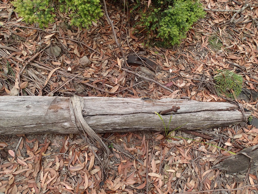
Fig 2.3 – A prop leg with its single bolt still in place. The top of the leg has been tapered to fit between the two main legs and the bolt acted as a pivot as the tower was pulled upright then held the prop in between the main legs.
The cross-arm was held in place with a head-plate and supported by two right-angled brackets made of cast iron. The head plate was held in place by 6 bolts, which went right through the angled legs. The right-angled brackets were held by bolts which went transversely through the angled legs and also up into the cross arm.
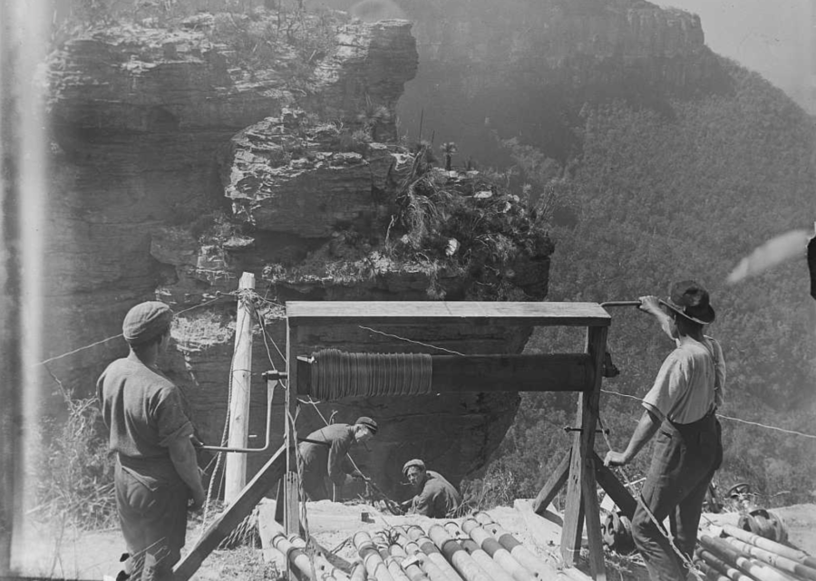
On top of outside ends of the cross-arm were bolted cast iron saddles which supported the track ropes and allowed them to slide back and forth. These saddles were of varying lengths depending on the load and the deflection angle across the tower.
Seven feet below the cross-head were two timbers bolted either side of the angled legs. These supported the haulage rope wheels and a “gathering plank” which was there to stop large swings of the haulage rope caused by cross winds, and to ensure that the haulage rope dropped onto the roller. Ladder rungs were nailed to the prop leg.
These tripod towers were approximately 30 feet high and approx. 50 yards apart depending on terrain. The gauge (distance between the centres of the track ropes) of the ropeway was 6’8” so the cross-arms were 6’10” long and were cut away underneath for clearance of something(?).
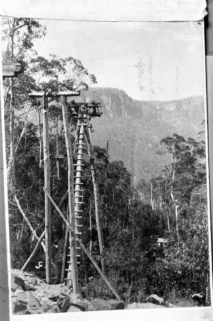
There were variations on these tower designs, the one shown in Fig 2.1 has a double head. This was to deal with large changes in track rope deflection. It consisted of an extra set of angled legs sprouting from just above the haulage rope cross bars, clamped at the top with a head-plate and angle brackets. On top of each of the two cross arms was bolted a square section iron bar, with a wheel turning on a stud at each end. The wheels were 6” in diameter and with a groove suitable for the two sizes of track rope. The two cross arms were spaced apart with two round bars approx. 1” in diameter and 6’ long. There were 4 of these arrangements used in varying configurations, Towers 10, 13, 19? and 44-45.
The next tower design was a simple Tee, (fig 1.42) only 7’ high with two angled sawn timber legs, a cross-arm with head plate and right-angle brackets. The bottoms of the legs were spaced with 8”x1” planks on either side, with the haulage wheels on the ground underneath. The tower was angled to equalise the track rope angle on either side.
The 2 legged “approach tower” in Fig 2.1 appears to be a later addition to further ease the change of angle across Tower 45.
Assembly and erection.
Firstly, the two angled legs are laid out with their bases just uphill of the holes dug to stand them in and their tops uphill. Their tops are supported on a strong sawhorse to make assembly easier.
Because the cross arms had already been drilled at Gladstone, as these sawn timbers were re-used complete with saddles, the brackets would be bolted to the cross arm, then the pole tops cut away – probably with axes – so that the brackets fitted on either side and the head plate fitted over them. Then the holes for the clamping bolts would be marked, the brackets removed and the 12” deep holes drilled with a brace and bit coming out exactly to line up with the bracket on the other side. The brackets and cross arm are then bolted into place.
Next the head plate is fitted, and these 6 holes have to be drilled through 6” of leg and cross arm, lining up with the hole on the other side. These guys were master craftsmen!
The prop leg was cut away for its top to fit between the angled legs and a single 1” bolt drilled all the way through all three legs, a 30” deep hole! This bolt acted as a pivot as the assembly of legs was pulled upright – probably using a portable winch called a “jungle devil” – and the base of the prop leg was dragged out to its hole.
At some sites, where it was rocky, only a small depression was cut for the base of the legs, and they were held in place by a wall of stone blocks.
Remember, every piece of equipment had to be carried to site by hand, the country was too steep for ponies. Inclines were used with crab winches in the steeper sections, evidenced by remaining lengths of web rail.
Track ropes.
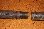
The track ropes were of at least three different sizes, 13/12/6/1 32mm diameter, (Fig 2.4) and 12/6/1 30mm diameter (Fig 2.5) and 12/6/1 25mm diameter. They were in 100 Metre lengths and each end was fitted with a Bleichert patent screw coupling (Fig 2.6).


Total rope weight something in the region of 30 Tons.
The Bleichert couplings, or track rope joiners, posed a particular problem when being re-assembled. They were designed to be screwed together using a double threaded ferrule, RH and LH so they could be screwed together in one operation. They were then prevented from unscrewing because of the natural rope twist, by drilling a hole through the threaded section using a hole already supplied in the outer of the socket, and then inserting a soft metal pin through and peening over the ends. Reusing these holes would be impossible because of misalignment of these holes unless every ferrule and socket were individually marked to keep the sets together. Hence the reason for quite a few of these joints not having pins reinserted when the ropeway was reinstalled.
Removing the track ropes from Gladstone would not be easy. Firstly, the lead filled cast iron tension weights (Fig 1.23) would have to be unloaded from their cradles. How do you then get 2 tons of cast iron blocks back to the top of the cliff? The same way that you got them down, with a crab winch mounted on Gladstone Lookout. A lovely flat rock with a sheer cliff underneath, ideal for such an operation. Then starting at the bottom, the track ropes would be lifted out of their saddles and lowered to the ground. Bearing in mind that this operation is not taking place on smooth flat ground but on a steep rocky slope. Then the rope sections have to be separated.
First the old pin would have to have the head filed off and driven out, and the ferrule unscrewed, separating the lengths of rope.
Then the haul rope would be used to winch out the lengths of rope, a threaded plug screwed into the socket with a chain attached. The chain would be “snaffled” around the haul rope in front of a spider, and then easily pulled out of the valley.
Seeing as our previously mentioned journalist noted many lengths of rail lying on the ground, at the opening ceremony, we can assume that there was spare rope on hand.
Pells and Hammon wondered where the extra track rope came from to make up the extra 3000 feet of travel needed for the Ruin Castle installation. Maybe it was there anyway, Bleichert being aware of the failure rate of wires on their track ropes. In 1881 Schulze and Wagemann erected a ropeway across the Yarra River in Melbourne to move soil for the abutments of a bridge. It is possible that some of the equipment came from there. http://nla.gov.au/nla.news-article5970943
The haul rope is the last to come out, the splice cut first, and the winder used to feed the rope onto hand-fed wooden reels. Quite a job, I have personally hand wound 1200 feet of 7/8″ rope onto a reel, and it takes four men, about 3 hours and a lot of sweat.
I imagine reel sizes were governed by what could be lifted and transported. The haul rope could have been “figure-eighted” on a flat top dray, that would be possible as the transport distance was only about 6 miles.
Rope installation across the Jamison Valley.
The general plan is to install the haulage rope first then use it to pull the lengths of track rope into position, screw the couplings together, and lift the ropes up onto the saddles in the cross arms.
Wire ropes run downhill very easily, all that is needed is a man walking downhill to guide the leading end and a braked feeding mechanism. However, as this system goes both up and downhill what was probably done was to feed two lengths of 8-gauge fencing wire across the valley, one on each side of the towers. The uphill end could be pulled by a team of men, then wind the Western side up onto a crab winch at the Mine end, pulling the tail of the haulage rope across the valley around the turnwheel then use the winder to pull it back again with the other length of fencing wire. Communication is the problem with this operation as the winch has to feed the right amount of rope as the wire is pulled from the Mine end. This may have been done with flags, a man perched on top of a tower in sight of the next man with two different coloured flags, would achieve the object. This has to be done twice, once on each side, (East and West) and the wire on the Eastern side then used to pull the tail of the haulage rope back from the mine to the winder. [The ropeway ran anti-clockwise, empty buckets on the Western side going out to the Mine and loaded buckets coming back on the Eastern side.]
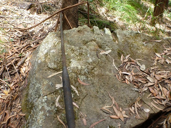
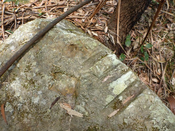
Then the haulage rope is spliced to make a complete loop and the winder can be used to pull the 100M lengths of track rope into position resulting in these grooves in the rocks as they are dragged across them. (Fig 2.7)

The Gladstone rail siding return sheave (Fig 2.9) also posed a problem with disassembly and re-deployment.
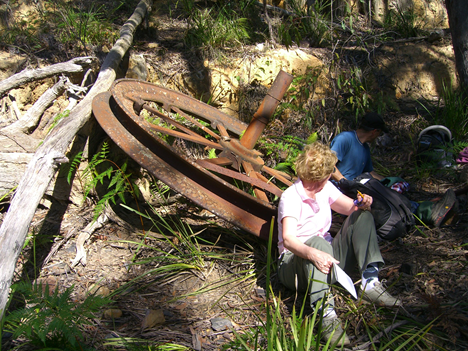
The spokes could be unbolted, and the rim separated from the shaft, but the rim is in one piece, providing an unwieldy load. The Gladstone installation had two return sheaves, one in the valley and one at the Railway Siding. Fig. 2.9 is the Railway Siding one now remaining in the Megalong Valley at the site of The Glen Shale Mine. The one outside the Gladstone mine is still in situ, but needs to be exposed, measured and photographed. Fig, 1.6 and 1.7.
It would be logical to re-use the one at the Northern end, which was much more accessible. However, this sheave had to be transported to the Ruin Castle mine site before the haul rope could be installed. There was only one practical route, and that was over the cliff off the Narrow Neck. We have recently (June 2020) discovered a cutting on the top of the Neck(Fig 2.10) which is angled in the right direction and which may have been for clearance for a flying fox to carry heavy equipment down into the valley near the mine site. Lat 33 45 07 Long 150 17 01. However, I have not been able to locate any bolt holes or fixings at the edge of the cliff where such a flying fox would have to have a small tower or davit.
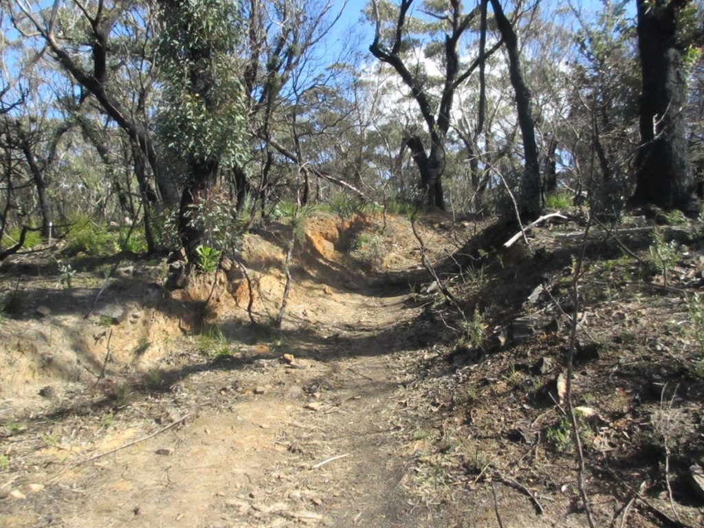
The sides of the cutting are well fallen in, indicating great age. The fill from the cutting has been dumped at the bottom of the cutting to provide a platform, big enough to turn a horse and cart around.