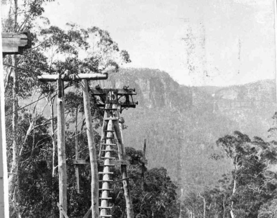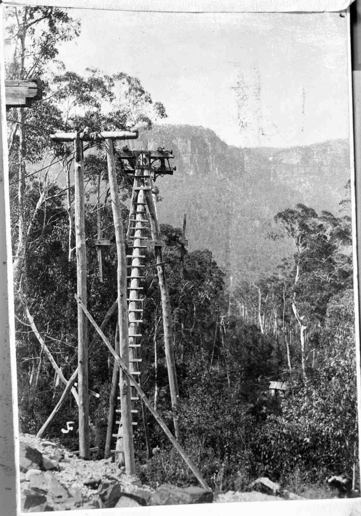
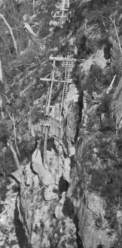
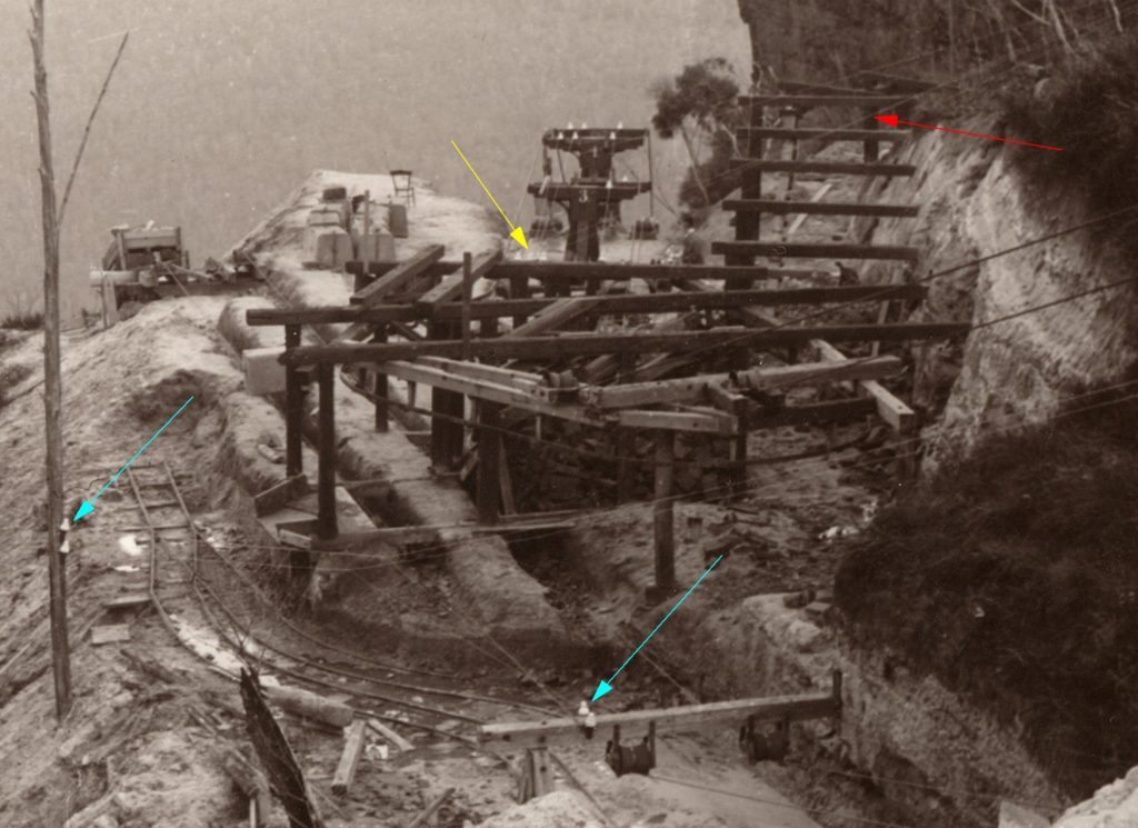
A high resolution version of Fig 3.1 is available for study
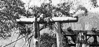
This is the only photo that we have of the Southern or Mine end of the Ropeway, but we can deduce quite a lot from it.
This photo (Fig 3.1) was taken about 1903, before the bushfires of that period burnt down a lot of towers. The photo is signed JF. I still don’t know who this is, despite many enquiries. The photo is held by BMHS as a 6×4 postcard, but a hi-res scan shows a lot of detail.
The Outbye rope is still in place, the Inbye rope is not. The haulage rope is not in place. The telephone wire is still in place. [ It was probably used by AKO&M to communicate with the Northern end 1892-1895. The Outbye rope may have been left in place to provide a return circuit for this, and the circuit crossed to the Inbye rope at the tension station.]
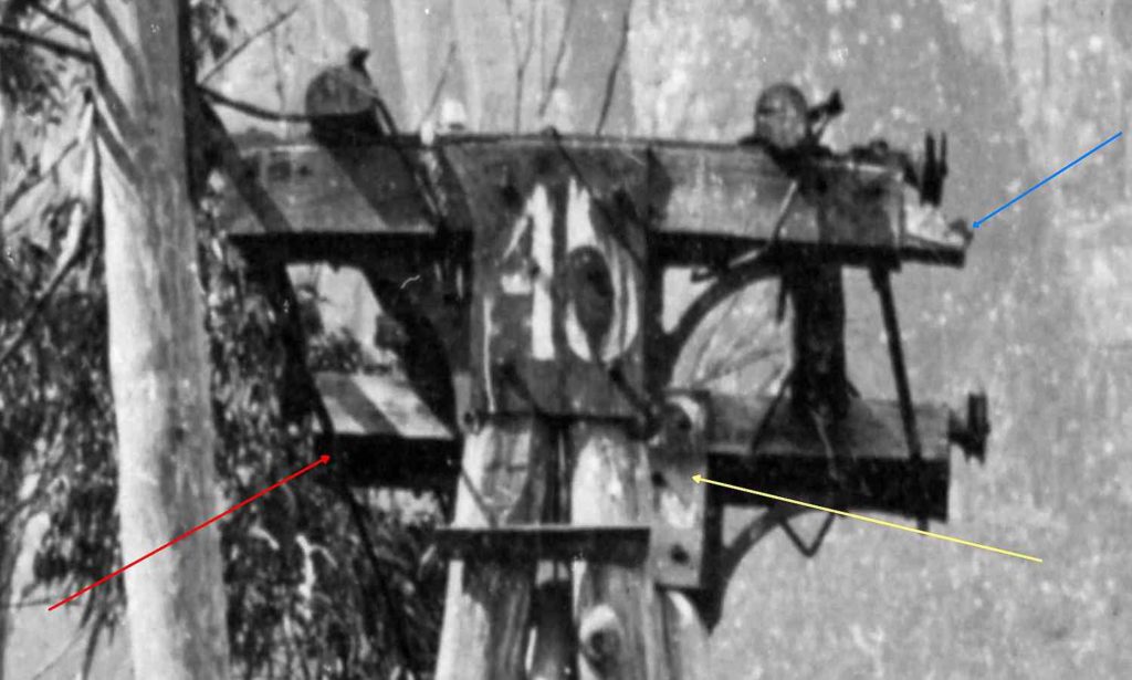
The Outbye rope is only supported on one of the two wheels on the tower top, it can be clearly seen passing under the far side cross member. (Red arrow Fig 3.2). Towers: The closest timber (Fig 3.3) is probably the last support before the transport rails begin, the rope slipper can be seen at its end. It seems to have had a piece of timber added on top, possibly to improve the rope’s alignment with the terminal railings. These timbers are sawn. Generally, all tower legs are native timber, and crossheads and haul rope idler mountings, and wind deflection arms are sawn timber. Ladder rungs are split native timber. The haul rope idler timbers show extra boltholes, indicating that have been re-used from Gladstone.
The next tower, (Fig 3.4) a two-legged Tee tower, has been tied with a sling to prevent it pushing over from rope forces. The left-hand leg has a fabricated clamp over the top, the right-hand leg has a bracket on one side. The cross arm has a rope slipper on each end. The two legs have cross-arm lateral bracing. This tower is made entirely of round native timber. It appears that the purpose of this tower is to relieve load on Tower 45.
Tower 45 has obviously had some serious damage done to it and major repair work done.
- There are additional round timbers bolted across the two main cross members. These timbers are clamped in place with U shaped clamps and a flat bar held with two nuts. They pass through the “window” of the right-angle brackets.
The number on the top piece is wrong, it is 42 (Yellow arrow Fig 3.2) it should be 45. It has been scavenged from another tower. Possibly the next tower down the line which does not have a cross member and is only supporting a single insulator. It appears that this tower had uplift (the ropes were lifting out of the saddles), so it could be abandoned. I think Mr Schulze would have been pretty pedantic about things such as numbering! The Germanic Script used for the numbers is noted.
- Both the haulage rope wheels are not originals. They have both been replaced with standard parallel rope rollers. There are quite a few of these at various tower sites across the valley, it appears that buckets striking and wrecking these rollers was not an uncommon occurrence.
- The prop leg of this tower is on the uphill side, all the other towers have the prop leg on the downhill side.
- A rope appears to be tied around the RH leg just below the right-angle bracket.
- There is something sticking out of the RH side of the tower top. Blue arrow.
The two wheels that carried the Inbye track rope can be clearly seen.
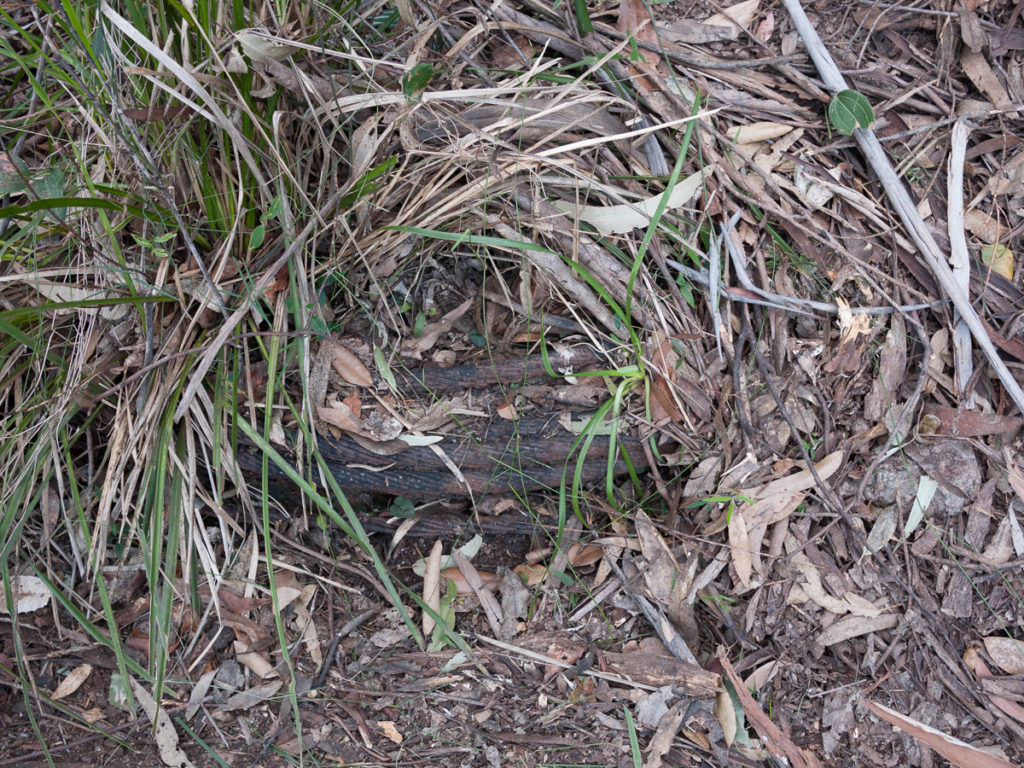
A modern photograph of the tower head lying among the grass shows more detail: –
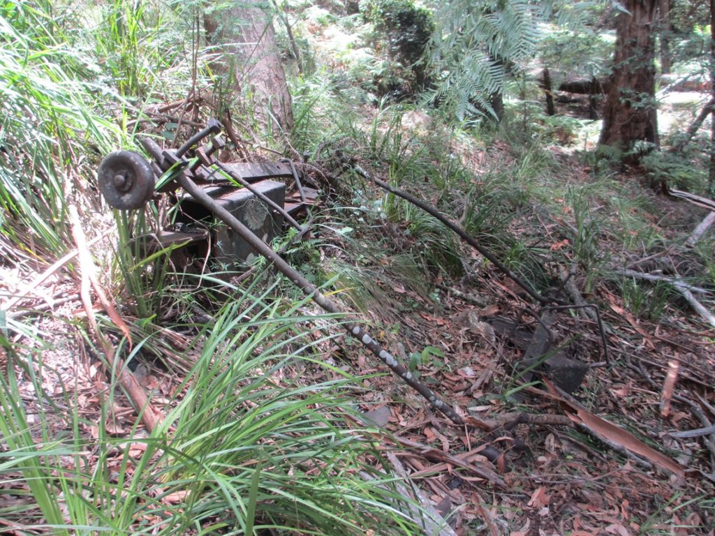

Here are the two tower heads with the rods joining the front and back together, the four clamps through the right-angle brackets. The recess on the underside of the bar, was to clear the tower head steel. The Western tie bar has been severely bent as the tower fell, but the Eastern one is still pretty straight.
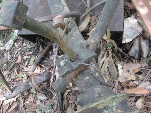
Washers must have been in short supply, so the blacksmith has lopped off a piece of strip with a suitable hole in it to make up the space and allow the nut to tighten. (Fig 3.7)
It is very unlikely that this tower head fell to the ground in the upright position as shown, I think bushwalkers have engaged in a bit of restitution here.
Back to Fig 3.1 -There is a miner’s hut to the right of the next tower. We have located the site of this hut by its ash pile and fireplace remains.
The next tower has no crosshead or haul rope idlers and is built with the tripod leg downslope. The telephone wire insulator is mounted on a small timber at the top. The crosshead could have been removed because of uplift on the track ropes. i.e. the tower was unnecessary.
The next Tower appears to be numbered “44”.
The large white splotch in the medium background should be the top of the hill on the Northern side of Cascade creek.
Katoomba Falls can be clearly seen in the right background [ and the fingerprint of the photographer]
The Site of the Southern terminal
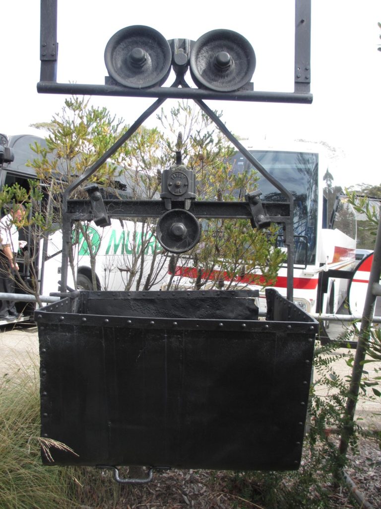
Unlike the Gladstone installation, the Southern terminal came in at a level below the mine. This means that gravity can be used to load the buckets down a hopper and chute arrangement. The double bucket trolleys from Gladstone could not be used at Ruin Castle because the Shale Seam was too low at only 24”. Special low skips were used.


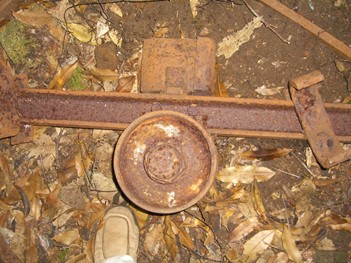
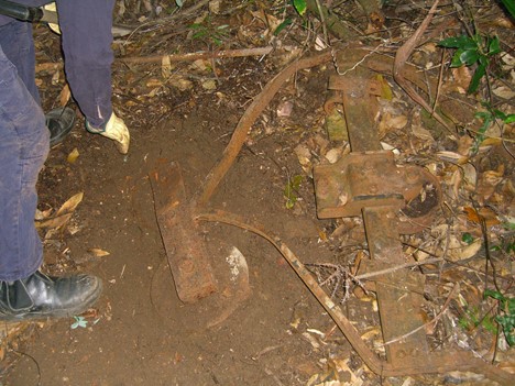
Fig 3.8 -This is the frame of a 2’ high shale skip built for the low seam in the Ruined Castle Mine with a sideways opening front door.
Top Left photo – the back frame
Top right photo – the front door latch
Bottom left photo – the door hinge
What is today the walking track of the Federal Pass, was Mr Duff’s pony tram track of 1892. After it passes the main adit, the Westward rise of the seam was used to advantage, in that, the skips carrying stone to be dumped, could pass over the top of the pony track which continued on the same level. If you take a short off track excursion at this point, you will see that the hill side is made up of broken rock which has come out of the mine. These skips could also dump into the pony skips.(It also meant that water drained out of the main adit, a considerable asset!)
When the ropeway was operating, I don’t think that ponies were used underground mostly because of the low seam height. They may have been used to bring the skips to the ropeway hopper from the “tipdown” points.
The ropeway was terminated by the carriers being transferred from the track rope to the transfer rail, which diverted them around the 6’8” Diameter Haul rope return wheel and the track rope anchors, through a semicircular trench cut into the hillside about 7 metres below the level of the tram track. Halfway around the trench was the loading hopper. It would have been a very unpleasant job pushing the carriers around that rail, and stopping the bucket under the chute, then pulling the lever to dump the shale into the bucket. Shale dust is particularly fine and choking. Imagine the mud when it was raining!
One quarter of the way around the trench there was a RH branch leading to the carrier storage area. This flat about 10M square, and was later used as a pony stable and connected to the tram track level by a ramp.


Bleichert track rope problems.
The Bleichert Aerial Ropeway installed near Katoomba, in the Blue Mountains, Australia, operated from 1889 to 1892 before the out-bye track rope broke on Sat 23rd April 1892, after which It was abandoned.
One of Bleichert’s strong selling points was that the carriage wheels would after a time, smooth out the ripples in the track rope, and make for quieter and more economical running.

A second point was the ability to use different sized track ropes in the same span, using his joining ferrules, and hence be able to use a lighter rope toward the centre of the span where the tension was less, and hence be cheaper.
This was a powerful argument but had a couple of serious flaws.
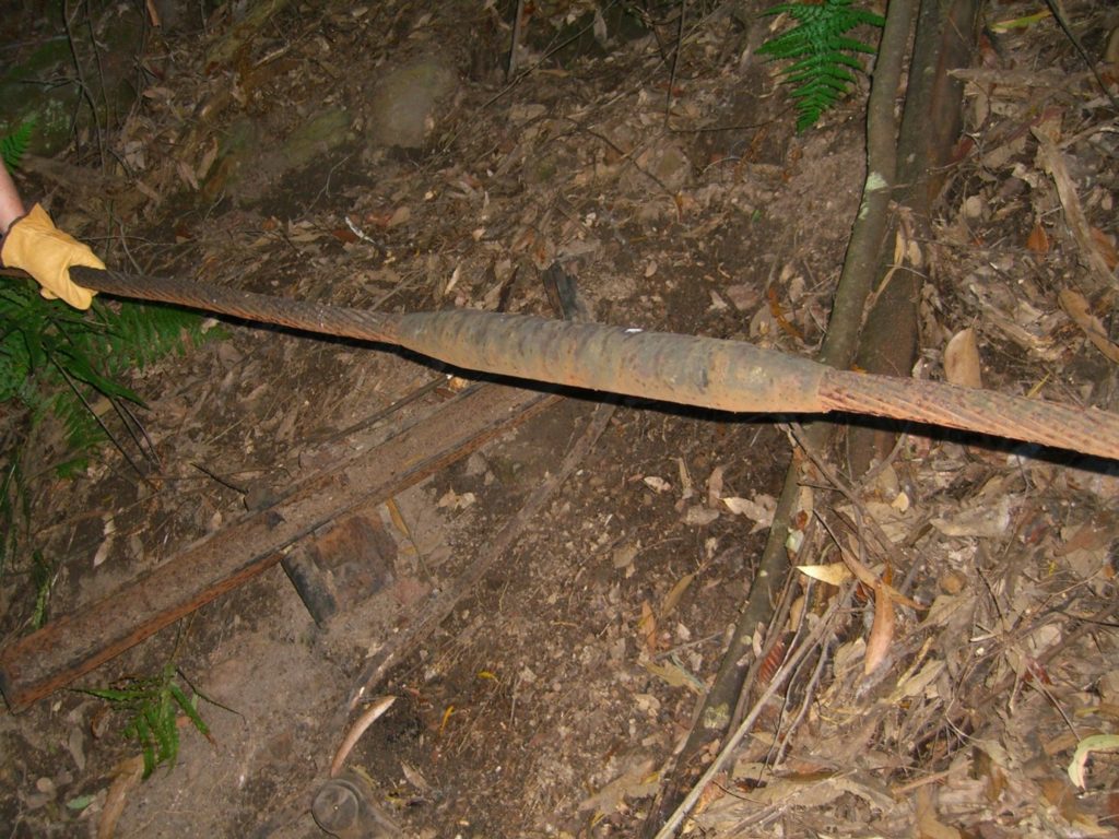
The iron used in the ropes was crucible steel, of questionable quality, roughly of 90 TSI, (Tons per Square Inch) and hardness of 193 HVS. The ropes were all a right hand lay of a single strand of sometimes varying wire sizes, construction of the two used at Katoomba were 13/12/6/1 and 12/6/1.
The 2 carriage wheels were of cast iron, and the groove radius of the wheel was 30mm. This radius had to be sized to pass over the rope joiners with a diameter of 58mm which joined the ropes used in Katoomba’s system, the inbound 13/12/6/1 of 36mm (1 7/16”) dia. The outbound rope 12/6/1 34mm (of 1 ⅜”). This produced some very high contact pressures on the smaller ropes. The outbound rope approaching the tension station was a case in point. As this was the lowest tension in the span, a 25mm diam rope had been used. There is a reel of this rope beside the tension pit, 1M dia. and 400mm high, making approximately 100 M. This piece of rope is very corroded because of it resting on the ground and being constantly wet. Because it was on a reel it is likely that it was a new piece. Possibly awaiting the time to replace the expected damaged piece.
As the wheels ran on the rope, the outer wires experienced some “cold flow” and the wire material was pushed away from the top of the wire producing a flattened strand. Just as the salesman promised! Where the span was long enough to allow the rope to spin a little, this produced an almost complete flattened strand, but where the rope was in a saddle it was an entirely different story.
The villains in the piece were the feathers produced on the work hardened outer edge of the cold flow, – (Red Arrow Fig 3.12) – which, if the rope was bent appropriately, propagated into cracks that resulted in rope failure, coupled with the effective reduction of cross sectional area of the wire, the cold flow section now hardened from 193 HVS to 244 HVS and was not contributing to the rope’s strength.
In an ordinary span, the rope was bent toward the flattened wires, hence not stretching open the edge cracks on the cold flow. But, on a saddle exactly the opposite occurs, bending the rope away from the cracks, and propagating the cracks into the wires.
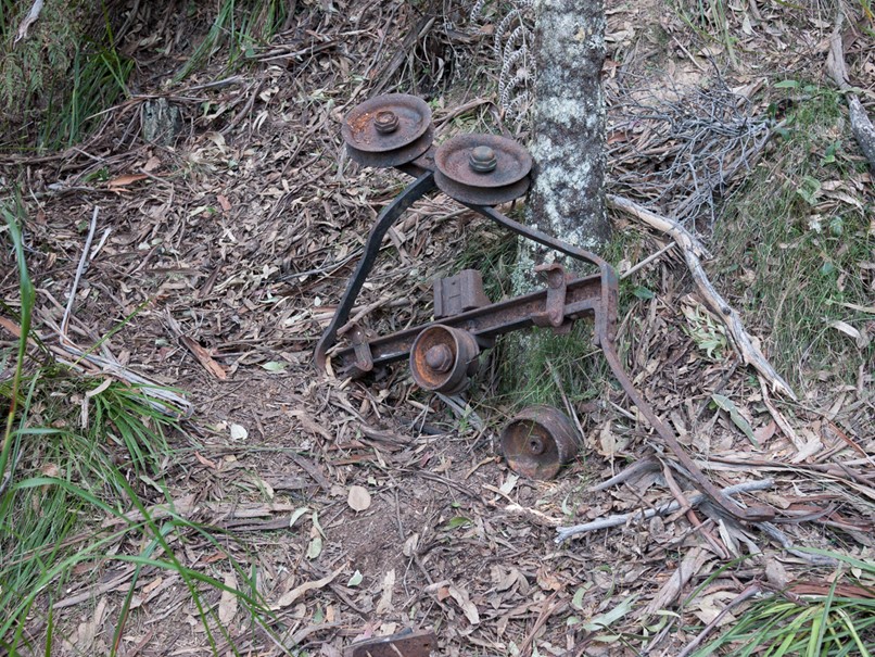
Bleichert used three methods of supporting the track ropes on the tower cross arms. The first was cast iron saddles, of two lengths, 260mm and 500mm. The second, where a larger amount of cross tower movement was expected, was a small 4 wheeled truck on a rail, clamped to the rope with a saddle, the truck expected to move back and forward along the track of 300mm, to allow rope movement, and theoretically prevent damage from sliding across the saddles. Both the tracks that we have found have had the stop at the end broken off, indicating that they didn’t deal with the problem of unexpected over-travel very well.

The third was used where there was a large deflection across the tower, and it used a double topped tower, and two cast iron wheels 120mm in diameter, about 2 metres apart, for each rope. This is a very small radius to bend a rope of this nature. Four of these were used, one as the first exit tower at the Southern loading terminal end, the second as the exit tower for the Southern end of the tension station, the third at the top of the cutting Tower 13, and the fourth, suspended from a very innovative tower No. 10 built on a series of ledges on the side of a cliff.
Another contributing factor to rope damage at the saddle was the method of coupling the buckets to the haulage rope. Normally as a bucket moves across a span between towers, if the track rope could not move, the tension could increase up to rope break. This is allowed for by the rope being able to slide across the saddles and increase the length of rope in a span, and hence reduce the tension, at the same time reducing the length in the adjacent span. As the bucket approaches the tower the rope slides back again. The buckets were attached to the haulage rope using a slug or spider, at fixed intervals along the haulage rope, to which a fork in the rope grip engaged. The end result of this was that on a given saddle, because of the regular spacing of the buckets either side of the tower the track rope always returned to the same place in the saddle as the bucket passed over it and so confined the damage to a particular spot on the track rope.
As the carriage approaches the saddle, the catenary flattens, and the rope lifts from the ends of the saddle, effectively straightening the rope. The first carriage wheel passes over the saddle, putting high pressure through the rope wires into the saddle. The same cold flow process also results in the cross section of the internal wires changing as they are crushed together. Depending on whether there is a wire or a valley at the top of the saddle, and on the rope configuration, different types of damage occur inside the rope. The 12/6/1 lay could have a wire at the top and hence a wire resting on the saddle, and a line of thrust straight through the five wires. If the 12/6/1 had a valley at the top, the squeezing of the wires produced some very strange wire shapes!
Back to the saddle transition. As the first wheel passes beyond the saddle, the rope is again bent around the saddle because the wheels are further apart than the length of the saddle. The back wheel now passes across the saddle, lifting the rope away at the approach end and straightening it again. This working of the cracks in the feathers on the upper wires, results in metal fatigue, propagation of the cracks, and wire failure. With a travel speed of 2M/sec this fluctuation occurs very quickly.
The wire would break right at the top centre of the saddle where the pressure was highest and wire damage greatest. The immediate effect of a broken wire was lifting out of the lay. The up-direction wire would be pushed back into the lay by the passing carriage wheels, but the down direction wire, ran the severe risk of being caught and dragged forward along the rope. Depending on how long the saddle was, the down direction wire could be held underneath on its lay, and then the net effect was to break it off.
The ultimate cause of the ropeway failure was tower, No. 7, right on the edge of the cliff, where the outbound rope rested in the saddle. The anchor being only 50M away, there was very little movement across the saddle, and all the damage was being done in the one spot. When the upper wire failed, it must have been noticed quickly and the drive stopped before too much more damage could be done. The immediate damage control was to put a clamp around the rope to prevent further unraveling of the broken wire. Our photograph Fig 2.9 shows the clamp in place with the drive still operating. On Saturday 23rd April 1892 the rope broke, and the clamp and the rope went over the edge of the cliff and into the valley 150M below. The aforementioned damage to the internal wires at this saddle was also a factor in this failure, they were unable to be inspected in any way. (still a problem today!)
The report in the Katoomba Times of 29th April is quite brief viz:
Last Saturday a very serious accident occurred at the Katoomba Mines to the suspended tramline from the cliff to the shale mines. The wire rope bearing several skips laden with shale and provisions broke and participated a great number of the skips into a creek in the valley, besides doing great damage to the line. Luckily no one was riding in the skips at the time; if that had been the case the result must have been fatal. However, matters are very serious as it is, for, we understand, nearly £400 worth of property was destroyed. It is great pity the rope did not hold out a little longer, as it was only intended to use this system until the completion of the tramline to the ruined castle portion of the A.K.and O. Company’s property, which is under the care of Mr. Duff, and is progressing favorably.
It Is not stated if the break occurred overnight or while the Ropeway was operating. Being April, cold overnight temperatures probably were not a factor in creating rope shrinkage and hence increasing rope tension, so it is more probable that fatigue was the culprit, and the passing of a bucket across tower 7 with the resultant bending of the wires and a crack in an internal wire opened up that little bit more reducing the cross sectional area below the point of yield, and the wire broke. This produced a cascade of wire breaks as the tension on the remaining wires increased above their yield point.
See figs 69, 70 and 71.
Aftermath of the rope break.
When the rope broke there would have been a huge physical shock run through the system. The engine driver would certainly have felt it and shut off steam as quickly as possible and get what brakes he had applied. The initial effect would be the outbye rope sagging between towers 10 and 9, and the rope end pulling through towers 8 and 9 and out of the carriages of any buckets that were in between these towers, and rapidly piling up in untidy coils at the base of the cliff under Tower 9. (It is still there today!) The tensioning weights in the tension pit would drop to the floor of the pit.
The most dramatic effect would be on the haulage rope, as suddenly it was bearing the weight of the carriers and buckets when the outbye rope was ripped out through the carriage wheels. The stated distance between buckets was 270 feet at the Gladstone opening in 1885. So between Towers 7, 8, 9 and 10 on the outbye rope, there were probably 4 buckets. The question is whether the haulage rope broke or not. The immediate effect when the buckets dropped so as the haul rope was supporting them, would be the tension trolley would be slammed up against its top stop. That tension trolley can be seen in the background of Fig 77, and the timbers that formed that top stop. If they failed and the trolley came further up, the tension sheave would be the next to “bottom out” on whatever was its travel limit. (Calculations have shown that there had to be at least a four-fall block between the tension sheave and the tension trolley). The net effect of all this was that a considerable amount of haul rope was fed into the system by the tensioning arrangement which probably saved the rope from breaking.
What we see today, lying on the valley floor, is the aftermath of that day, and the recovery operations that were undertaken.
Long before (in seconds) the driver could shut off steam, the outbound bucket between Tower 7 and 8 got dragged into tower 8. Here it is Figs 65, 66 and 67.

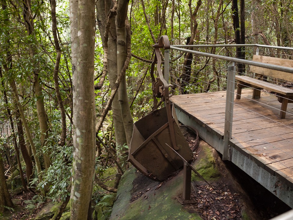
Only one of those other carriers from this dramatic incident has survived, and it is on display on the Boardwalk Coal Mine Village loop. Fig 67A. There are four other buckets along the main boardwalk all probably resulting from this incident.
The 3 remaining outbound carriers and buckets between towers 9 and 10, are now being dragged down by the weight of the falling track rope to the tangle at the bottom of the cliff below Tower 9. As a guide as to what this looked like, today you can still see the discarded inbound track rope hanging down the cliff, from the Cableway Cabin. There are three fallen carriers between Tower 10 and the Tension Station, but they all seem to be a result of on-rope collisions while operating. (See separate chapter.)
At the tension station there are two carriers, one Fig67B is a classic case of being dragged on the ground as the track rope tension dropped, with both bucket arms bent to the back . The rope grip slide survived undamaged, and the rope grip has been salvaged.
The most valuable item to be recovered was the shale in the buckets suspended above the valley. However everything beyond the tension station on the outbound side, and everything on the inbound side were still in perfect working order, so once the outbound side was cleared of problems, the buckets of shale could be winched in and unloaded, then pushed onto the holding rail, see RHS of Fig. 77 Red arrow.
Today there are approximately 66 buckets spread across the valley floor. Some of these were the result of misadventures during operations, and some the aftermath of the rope breaking. There are also 16 carriers, 2 of which we have recovered for display purposes. All the carriers are on the Northern side of Cascade Creek. from the outbound rope, North of the Tension Pit, the balance being recovered by AKO&M by winching them out. The two track ropes still lie across the full width of the valley, but the haulage rope has been recovered. Some of the track rope terminators have been salvaged for their white metal content; the rope just cut roughly through. Whether this was done by the miners or by later “entrepreneurs” is unknown.
Judging from the one photograph that we have of the Southern end of the ropeway, Fig 3.1, the outbound track rope was cut short also, and a piece removed, once the ropeway was decommissioned.
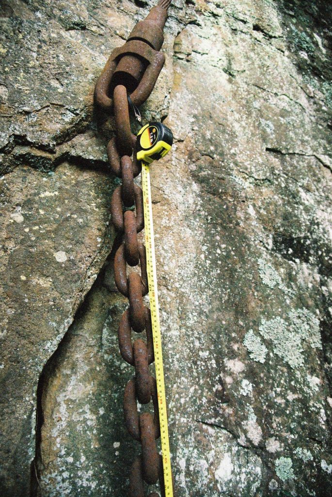
An attempt was made to recover a section of the outbound track rope and its attached counterweight suspension chain from the Tension Station. They got the tail as far as Tower 10 then lost it and it is now hanging over the cliff below Tower 10. (Fig 3.23)