Rope Saddles
There were 5 types of rope saddles used on the ropeway, with two different sizes of each for the inbound 25mm Dia. and outbound 33mm Dia. ropes.
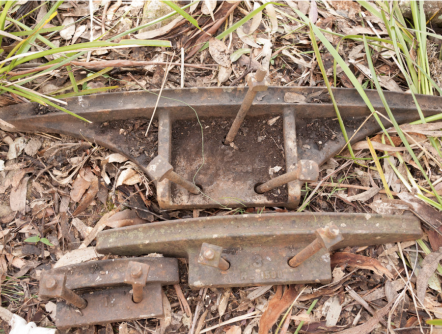
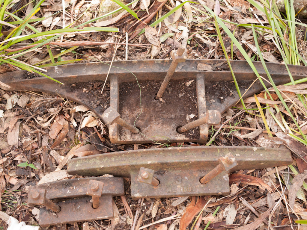
1: Cast number “0” 250mm long 40mm wide radius 350mm.
2: Cast number “1.” 250mm long 45mm wide rope radius of 500mm.
3: Cast number “2” 1M long with a rope radius of 2.5M.
4: Cast number “3 R-1500” 500mm long with a rope radius of 1500mm
5: Wheels on the double tower top;
Outbound – Width 1 ¼” radius 2 ⅝” Flange Dia. 7”
Inbound – Width 1 ¾” radius 2 ⅝” Flange Dia. 7”

6: Sliding saddle. Cast “PATENT”. Two sizes, Track 200mm and 300mm long – straight with stop at either end, Truck radius 350mm. Truck travel 150mm. A small cap kept the rope captive on the truck.


Standard practice today is to use a minimum of 40 x rope diameter for the diameter of a sheave and 200x for a rope slipper.
The double tower top wheels have 6x outbound and 4.2x inbound!!! This will result in very severe bending stresses on the ropes, crushing the wires together and damaging them.
Bleichert were obviously aware of the importance of using large rope radii on their rope saddles, they just weren’t conservative enough.

SURGE OR NO SURGE
One of the reasons for the large number of de-ropings could be rope surge. Rope surge is where accelerations of a section of rope are carried through the system, and sections of the rope slow down and speed up with the excess providing big sags in the longer catenaries.
This could cause the buckets to pass over a saddle at higher speeds than normal, creating conditions for truck lift off and bucket lift, as discussed previously.
What is unusual about this Katoomba system, is that it goes downhill on both sides of a creek, with the mine on one side and the drive on the other. The usual practice, in order to ensure that the haulage rope is always tight around the friction drive sheave, is to tension the outgoing or return side of the haulage rope as soon as it comes off the drive sheave. The weight of the loaded buckets coming up the hill to the drive, keeps it tight on the drive or inbound side.
This is done with a rope sheave mounted in a sliding carriage, that is attached to a counterweight. This system then copes with expansion and contraction of the haul rope with temperature change, and also with rope stretch as it is worked. It can feed extra rope into the catenaries to reduce the tension as a bucket passes between towers.

Now this works fine for a system that is all uphill or all downhill, but in our system, there is little or no control over the section from the mine to the creek.

The tension weight cannot be heavier than the slope component of the outbound haul rope tension from the drive sheave to the creek [ approx. 0.66 tons] plus the slope component of the empty buckets [3.9 tons – total 4.5 tons] or it will lift the rope up at the creek crossing and cause it to foul under the tower cross members. However the only need here is to maintain a suitable tension to guarantee enough friction for the drive to work (even with a wet rope) so the tension was generated with a skip on a slope, equipped with “hungry boards” and loaded with rocks. See fig 6.10. The basic idea is that even with no buckets on the outbound side, there still has to be enough tension to operate the drive, so the tension skip which I estimate would weigh about 1 ton, on a 30 degree slope, would exert approx. 500 kg. or 250kg of rope tension. Hence once the outbound rope was loaded up with buckets, the skip would spend its days sitting against the top stop on its incline, see fig.6.10 again.
The other problem is, at the mine end, that the loaded buckets that are running downhill from the mine, are pulling the empty buckets up the hill from the creek, an out of balance load of 2.2 tons, giving serious haul rope tension problems at the creek crossing, with slack rope on the inbound side and tight rope on the outbound side. See fig 6.12. There is a shoulder on the upper shaft of the return sheave, (see fig 6.11 ,6.12 and 6.13) above which a brake drum could have been clamped. [This sheave now resides at the Glen Shale Mine in Megalong]. A tricky balancing act to apply the right amount of brake without being able to see the rope at the creek crossing.


So, we have a poorly controlled 6kM long loop of rope weighing approx. 8.2 tons, 50 loaded buckets @800kg and 50 empties @ 300kg each – total 74 tons which are part of the system, moving at 2 m/sec. At the drive end its speed is controlled by the governor on the steam winder, which has a speed differential of +- 0.1 m/sec and a tendency to overcorrect. At the mine end, the speed of the rope is influenced by many factors as discussed and is certainly prone to surging speeds.

This steam engine (Fig 6.14) drove one of the sections at Chilecito. It is very similar to the engine that was used at Katoomba. The governor is hidden behind the cylinder but the control bar from it comes up to the link. ( Red arrow ) This is next to the damper ( blue arrow ) a 1904 improvement to limit over correction. The counterweight balls ( yellow arrow ) counter the weight of the governor mechanism. The regulator ( green arrow ) of which somebody has conveniently removed the slide valve so we can see the regulator slots inside. Regulators were highly evolved by 1904 and delivered a controlled amount of steam to the engine while only needing a small force to operate the valve, which a low speed engine like this one was all the governor could apply.
Note the flat belt drive in the background, the drive shaft is just clamped to the shaft, there is no key. The drive pulley is also constructed in two halves to allow field assembly.
Rope surge can be initiated by the connecting of a rope grip to a spider. At the drive end, the bucket is empty, so the inertia of the bucket and carrier is less, but if the carrier is stationary when the spider pushes into the grip, it must accelerate from 0 to 2 M/sec within a very short distance. This shock is taken up by the tension trolley and by tightening the catenary to the downrope towers. The spider separation is 60 metres, so the previous carrier is well beyond tower 9 when this happens, so a surge can easily be initiated. At the mine end, however it is a very different story. The rope here is being driven by the weight of the loaded carriers going downhill and when a spider engages, the shock load goes to the outbound empty carriers accelerating them. Then the whole lot recovers, and over-recovers, promoting surge.