Track ropes.
One of the big selling points of a Bleichert Ropeway in 1887, was, that as it operated, the ropes became smother, therefore operation became quieter and more efficient. This is a beautiful piece of spin doctoring, making an advantage of a fatal flaw in the design, the softness of the wires in the rope.
Here is an extract from the SMH of 13th July 1885, where the journalist was spruiking these advantages: –
These ropes are of a special spiral construction, formed of soft steel, in order to flatten out to a smooth surface after short use.
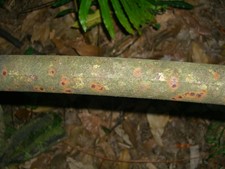
Some hi-res photos of an off-cut of each of the two track rope samples has revealed quite a bit about the damage resulting in their ultimate failure.
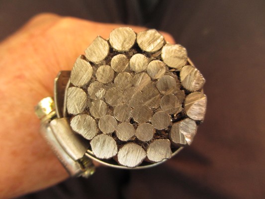
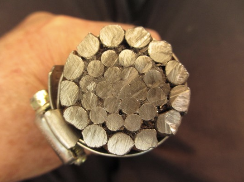
The 12/6/1 Fig 4.2 sample is a spiral construction, i.e. all wires are wound clockwise along the rope. All the different sizes of rope have this same simple spiral construction. (Technically these “ropes” are only “strands” as there is only one twisted member). Only every second wire of the outer layer is supported by the wire beneath it, the remaining 6 wires are only held in position by their form.
As the carrier wheels rolled along the rope, they deformed each outer wire in turn by “peening” the material from the “top” of the wire to form a flattened area with a feathered edge. This is not “wear” as in removing material from the wire, but a cold flow distorting the relatively soft wire.
Each of the wires that were supported by the wires beneath them suffered distortion to their cross section, in becoming oval, their dimension along the circumference of the rope becoming larger and their radial dimension becoming less. This also happened to the 6 wires in the second layer. The result of this was to squeeze the unsupported wires up out of the lay and hence expose them to even greater pressure from the carrier wheels. Note the gap between the outer wires and the next layer in Fig 4.2 illustrating this. In addition, the wire had to become longer to follow the helix and hence it was stretched, further reducing its Cross-Sectional Area (CSA) and hence its strength. Where the rope was resting in a tower saddle the damage was even greater, being on both top and bottom of the rope.
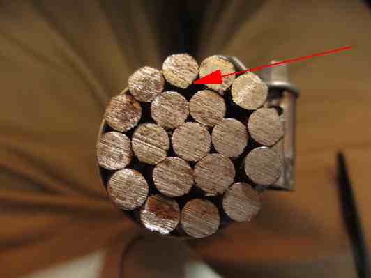
Note also, the topmost wire in Fig 4.2, how it is pointed at the bottom from being forced between the two wires below it. (Red Arrow) This particular piece of rope was retrieved from the concrete pit that the 1935 Scenic Railway electric winder was built in. It was being used as reinforcing for the concrete.
The ultimate failure of the rope was caused by the Micro-cracks that developed as the wires were “peened” by the truck wheels. Fig 4.1 shows only a slight effect, some wires got down to half the original wire diameter. See LHS of Fig 4.5. Where the rope was resting in a saddle, the rope was bent and straightened every time a truck passed over it. This had the effect of propagating the tiny cracks on the edge of the peening into the interior of the wire, resulting in its failure under tension.
Other problems resulting from this rope design, was the Bleichert assertion that different diameters of Track Ropes could be used in a single span, utilising the patented joining sockets, a larger rope could be used at the ends of the span, where the rope tensions were higher, and a smaller diameter used in the centre of the span, where the tensions were lower. An obvious cost saving benefit! An additional benefit was that the loaded buckets with consequent higher rope tensions could use the larger ropes, and the return empty buckets could run on a smaller rope.
This meant that the cup radius of the truck wheels had to be large enough to be able to run on the largest 33mm diameter rope and be able to transit the “Patented Joiners” without jamming. The end result of this is that when the truck wheels were running on the return 25mm small track rope, the contact pressure was unnecessarily high, because of the small contact area, and even more wire distortion took place.
THE EXAMINATION OF THE KING PHOTO (Fig 4.4)
Henry King in 1891. Photo MAAS.
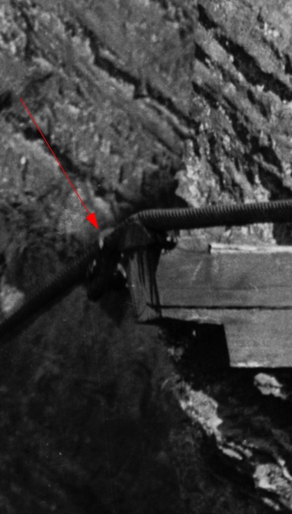
In April of 1892 the Outbye Track rope broke where it is resting on the RH saddle of this Tower No.7. Even though this Tower is not numbered. Note that the steel capping plate has a row of holes down the RHS. This suggests that it has been fabricated out of a water tank, and that some previous damage has been caused to this tower necessitating the replacement of the capping plate. The three photographs that I have of the ropeway show each tower carefully numbered using Germanic Script, it seems strange that this tower was not numbered.
Close examination of where the rope is resting in the saddle reveals the following: –
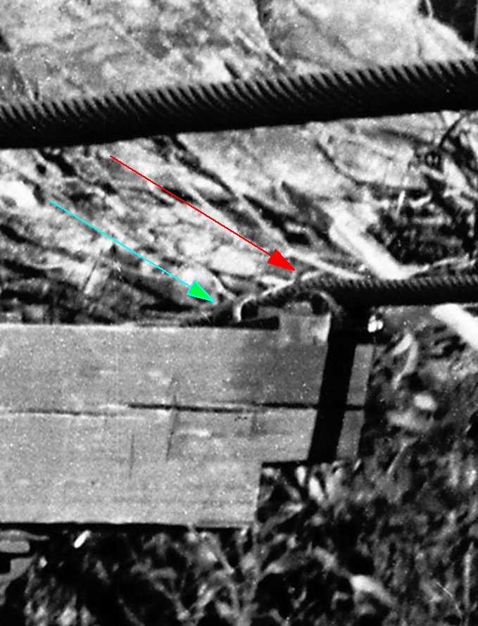
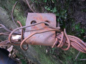
1: A broken wire can be seen sticking up on top of the saddle. (Red Arrow Fig 4.4) and a clamp can be seen around the rope just beyond the saddle. (Green Arrow Fig 4.4) This appears to be the same clamp still attached to the broken end in the Valley at the bottom of the cliff without any bolts through its 2 holes. Fig 4.5. It is possible that these two bolts were ripped out during its calamitous trip from the clifftop to the Valley floor, as it was dragged through Towers 8 and 9, but is seems unlikely that the ropeway would have been operated ( as Kings photo was taken while the buckets were moving – they being motion blurred ) without this clamp being properly secured with two bolts in place. It could be that further wires were breaking and coming unraveled at Tower 7, and that this was a further ”emergency” clamp, and that the rope broke before the poor blacksmith had time to bolt it up!
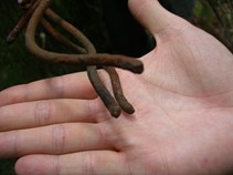
In Fig 4.5 the flattening of the wires can be clearly seen, and how its Cross Sectional Area (CSA) was dramatically reduced. As the cracks propagate though the wire, the CSA is reduced even further, and a classic tension failure occurs, evidenced by the slight “necking”, or reduction of diameter, of the wire at the failure point. Fig 4.6.
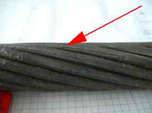
A further problem with these ropes was a factor completely unknown in 1892, and that was metal fatigue. As a rope is resting on a saddle and is being bent and unbent every time a truck passes over it, the inner wires suffer from fatigue and can break when they are under tension. Being inside the rope, these breaks could not be detected in 1892, and although the engineer would have been worried about the broken wires that he could see on the surface of the rope, he would have been a lot more worried if he had known that the inner wires were failing just as fast! Fig 4.7 shows one of these inner wires with a fatigue failure, being the closest one in the photograph.

2: The rope in the foreground of Fig 4.8 is the 33mm 13/12/6/1 inbound rope. At some stage this piece of rope was also replaced with 2 lengths of solid bar, Fig 73, in a similar way to the rope beyond Tower 12/13. Whether this was done before AKO&M started is not known. Fig 4.10 shows the Southern end of the discarded inbound rope with the same style of clip on it as the outbound rope, but this time with bolts holding it clamped on. This same clamp can be seen in the King photo just beyond the cross arm. Fig 4.8 Red arrow.
Obviously broken wires were a problem here too. Although these clamps served the immediate purpose of stopping the broken wire from unraveling further, they also created a further problem. As the truck wheel rolled over the clamp it drops onto the rope from the clamp in exactly the same spot every time, further exacerbating the problem by impacting the wire at the top of the rope and deforming it. Another thing to be noted from Fig 4.8 is the slight downward “set” in the rope just this side of the saddle. This is a product of the inflexibility of the rope and contributes to the vertical acceleration of the carrier as it crosses the saddle.
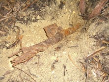
This round bar, Fig 4.9, is resting on the ledge below the site of Tower 7. The casting/forging mark on it can be clearly seen. This bar would have been hot rolled in a similar manner to railway line. This gear was dumped over the cliff in 1893 when the tramway to the Mort’s Glen Shale Mine was built and it was in the way of the re-routed haulage rope.
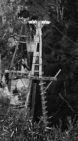
Tower 8, (Fig 4.11) which stood on the ledge immediately under today’s Cableway Tower, suffered from “uplift” where the tension of the track ropes downhill from the tower was high enough to lift the ropes off the top of the tower, which would make the carrier crash into the cross arm. This was solved by installing a 12′ extension on top of the tower. You can see the original top of the tower just under the bucket that is coming towards the photographer.
Insulators.
On the crossbar of Tower 7 there are 4 insulators. There are only three wires attached to them. What were they for?
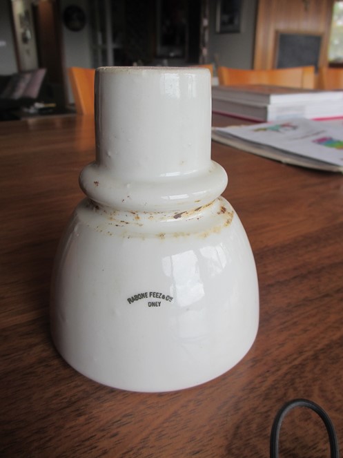
The insulators were made by Rabone Feez and Co of Sydney, Fig 4.13, a supplier of a wide variety of Mining equipment. Listed in 1892 Sands Directory as: merchants and general importers, agents for Hamburg-Magdeberg Fire Insurance Com. General Marine Insurance Co. (Dresden) and Board of Hamburg Underwriters 49 Pitt Street. The German connection is obvious as Oscar Schulze would have been ordering them.
Towers 8,9,10, 11 and 12 have three insulators each.
Tower 13 has two sets of three, because it had two crossbars supporting the track ropes, because of the large vertical defection at this tower, in order to go down through the cutting. Fig 2.4. There is only one on Towers 45 and 46 at the Southern terminal. Fig 4.12

The insulators supported one galvanised 8-gauge fencing wire each. These were used for communication back to the winder room.
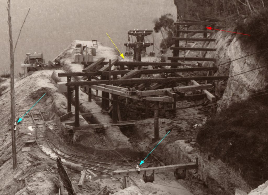
This photo Fig 4.14 (A stereo pair also by King) clearly shows the telephone lines. Three of them going up to the right to the winder room, (Red Arrow) and a separate pair coming down from the small incline winder that pulled the skips up the slope just to the right of the photo, and terminated on two insulators on the cross bar on the hold-down for the tension ropes, and also on a vertical pole on the left. (Blue arrows) From the SMH of 13th July 1885 the communication system used at Gladstone Colliery is described viz:
A telephone and electric signal bells (specially noteworthy as working without a battery) connect the three stations;
It seems from the two wires terminating at the crossbar that a telephone was being used when connected at these points, and also at the tension station only 300M distant. However, the distance to the Southern station at the mine was too great to work a telephone, so a single line operating the “electric signal bell” was used, utilising the track ropes as a return circuit.
Now CLICK HERE to go to Chapter Five, “the Rope Grip Mystery”.