There are 5 photographs of the Leura Filter Bed. Two of it under construction, and 3 of it operating. All of them contain figures for size comparison.
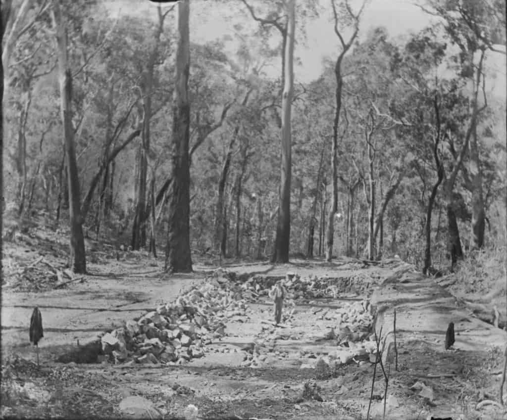
The pit has been dug down to bedrock, and a matrix of rubble filled trenches installed. The pile of rocks on the LHS is to become the boundary wall of large stone blocks that retain the filter material of smaller rocks.
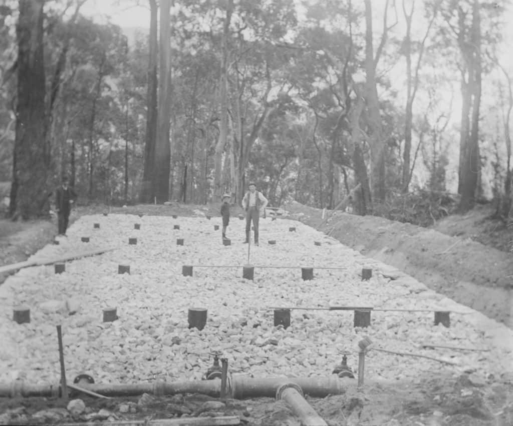
Fig 4.2 – The smaller rock filter material had been installed and the supports for the spray pipes are installed and are being leveled. The stone retaining wall can be clearly seen. The perimeter trench has been dug and a bank raised on the RHS. The supply pipe is in position.

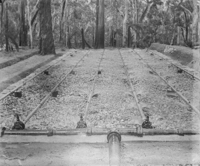
This photo is taken from the Eastern end. In the background the mitered concrete box holds the main shut off valve and acts as a thrust block to absorb the shock when the valve is shut, to avoid damage to the pipeline. There is a man standing beside the valve. The water pressure here would be in the region of 1000 PSI.

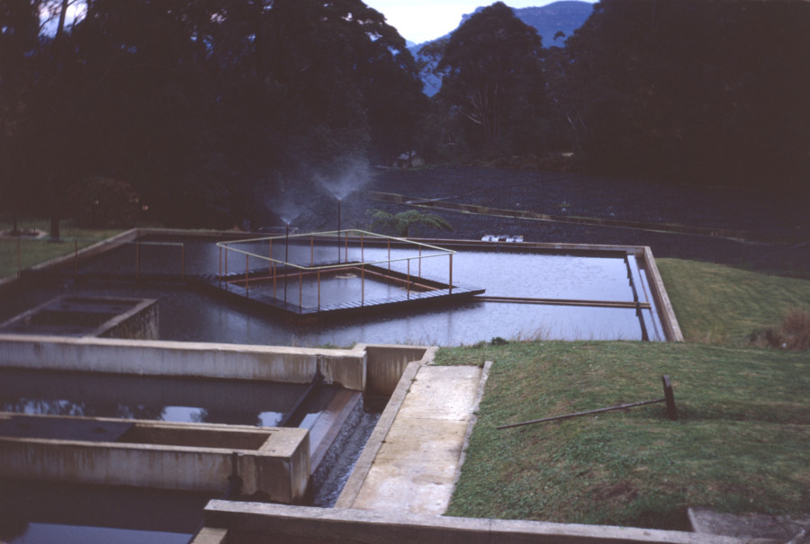
Figs 4.4 and 4.5 show the filter bed operating. The effluent from the septic tanks up on the clifftop, is sprayed onto the rock filter. It covers the filter stone surface with a thin film which can then be broken down by anaerobic bacteria. The effluent than trickles through the surrounding block wall, and into the surrounding trench, then through the dirt wall into the final drainage trench. (These are my terms, not a sewerage engineer’s). This is a more advanced design than the Katoomba Filter Bed.
There is an informative article on the history of sewerage treatment here:
https://documents.uow.edu.au/~sharonb/sewage/history2.html
and here:
https://en.wikipedia.org/wiki/Sewage_treatment
PHOTOGRAPHIC COMMENTS
Fitzgerald’s photographs were taken onto 5”x 4” glass plate negatives, probably using a Century Petite camera. https://photojottings.com/century-petite-no-1-4×5-camera-review/ or a Seneca No. 7. http://www.angelfire.com/ca/xanadu55/Collection.html
These cameras folded into a “pocket size”, as long as you had a very big pocket.
The exposure times were lengthy, hence the motion blur when handheld, and the lovely movement of the water captured in the creek beds.
There was no luxury of telephoto lenses, what you see on the ground glass screen is what you get. Focusing was by sliding the lens assembly along a track and watching the image on the screen. The Seneca had the luxury of a knob to move the lens. There was a pneumatic shutter trip available to avoid jarring the camera when tripping the shutter. A rubber bulb was squeezed, and a small cylinder tripped the shutter.
SEPTIC TANKS
There were two septic tanks feeding the two filter beds, one in Katoomba and one in Leura.
KATOOMBA
The Katoomba Tank is located in Katoomba Park approx. S33’ 43.401” E150’18.481”. It was placed parallel to the creek and is 1.15M wide and approx. 9M long. The cavity within is 700m wide and approx. 2M deep. It originally had concrete lids, the remains of some are still in the bottom of the tank. There are two breather pipes with ornate tops still standing. Next to the tank is the modern shaft connecting to the sewer tunnel installed in 1933.


There are small pieces of coal on the access track from Katoomba Falls Road, indicating that steam powered compressors and concrete mixers were used during its installation
LEURA
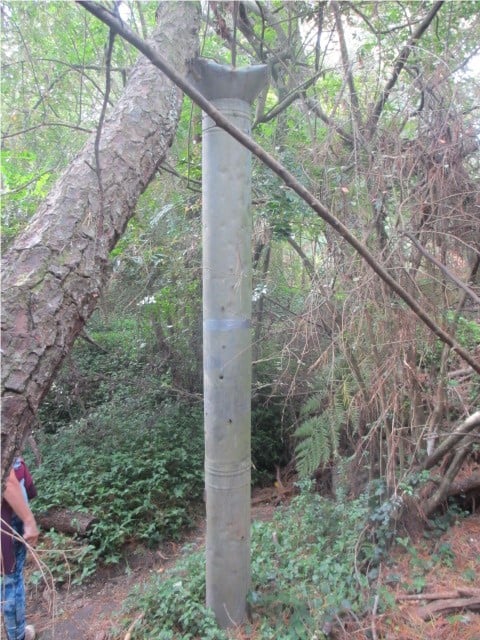
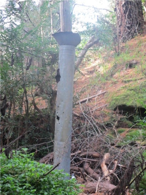
The Septic tank that fed the pipeline to the Leura Filter Beds was located upstream from Chelmsford Bridge approx. S33’ 43.044” E150’ 19.570”
Today, there are the remains of the original concrete tank and also a filter bed from a later date.
The original tank is orientated parallel to the creek and is very similar to the Katoomba Tank, 9M long 1.15M wide and approx. 2M deep.
The Leura Tank has been supplemented with a filter bed at some later stage, consisting of a large tank placed at right angles to the creek and connected to the old tank at the upper end. This tank is much larger, 1.5M wide, 9M long and 2M deep. It has a series of rectangular holes along the downstream side at the bottom of the tank, allowing sewerage to move into the filter.
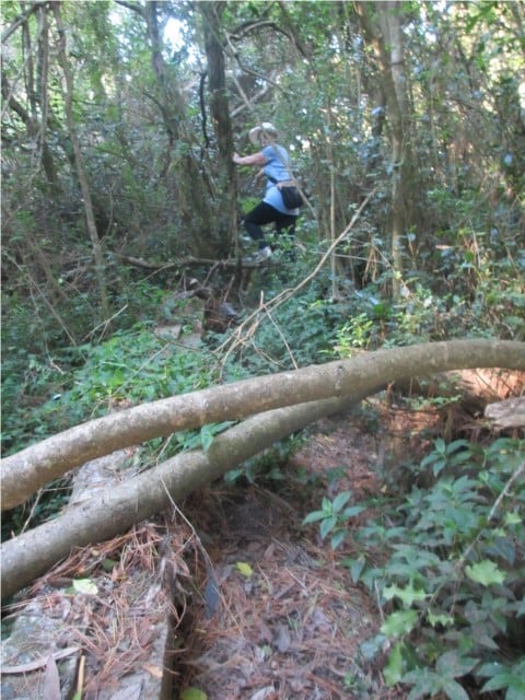
The old tank is used as a wall for one side of the filter, the creek side is probably also a concrete wall, but it is buried. At the bottom of the old tank a concrete wall has been built, also about 2M high, running at right angles to the creek, making a large box to contain the filter material. Today it looks like a nice flat grassy area level with the top of the big tank.
Below the wall, which also has rectangular holes to allow the sewerage to move through, is a large semicircular earth wall, forming a second filter. The sewerage filtered through this wall then ran into the creek.
I can only assume that this filtering system was used to supplement the filter in the Valley when the capacity of the 6” line was reached, the overflow was directed through this filter.
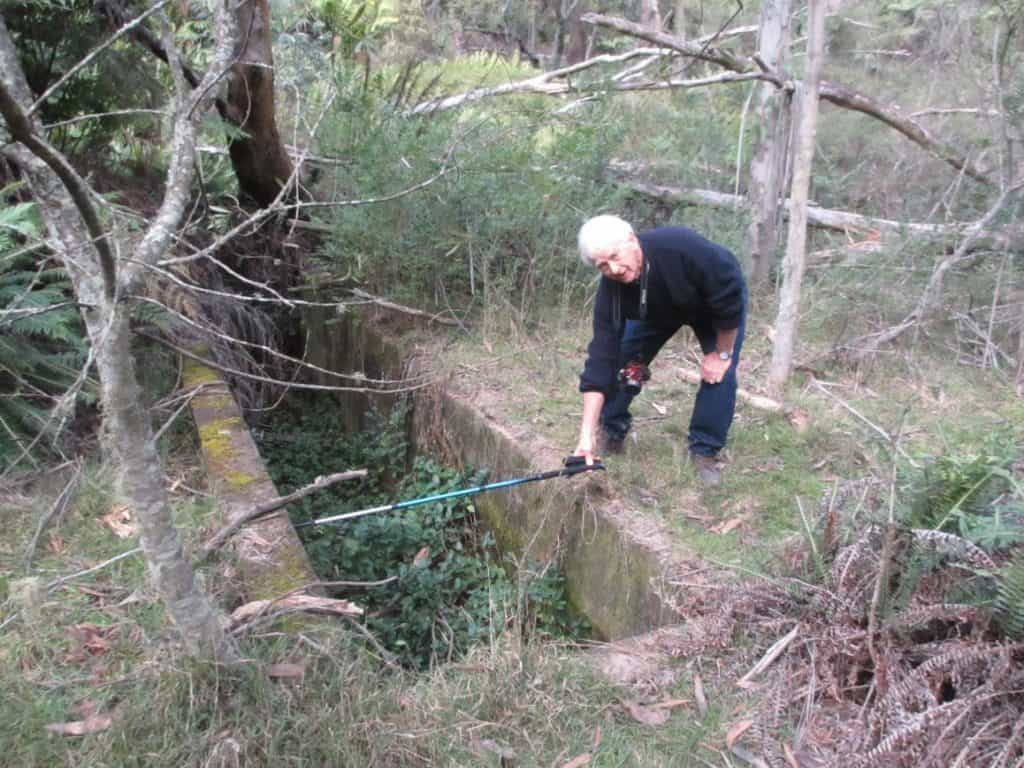
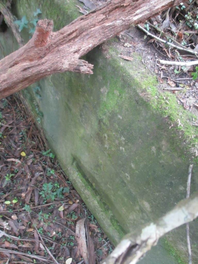

Fig 4.13 – Looking inside the exit slots. It seems that there are some flow control structures within.
Sewerage augmentation
In 1933 a sewerage augmentation scheme was commenced, wherein a tunnel was dug from the Katoomba Septic Tank to the Leura Septic tank and connected to an upgraded Leura Filter Bed. Poppet heads were erected above the three shafts that were used to construct the tunnel, to transport materials in, waste out, and men in and out. The three shafts were in Katoomba St. outside DP3614 lot 5 (No. 300). Outside the Community Housing flats in Darley St. DP2410 Lot 14 and on corner of Coomonderry and Stephen Streets and Dunmore Lane. The main workshops and compressors were at the Darley St site. Strangely no photos of these huge structures have survived.
A very detailed description may be found here http://nla.gov.au/nla.news-article190137560 and here http://nla.gov.au/nla.news-article190134395
At the same time as the tunnels were being bored, the Leura filter beds were being upgraded, and a similar network of flying foxes to Mr Fitzgerald’s was erected to transport and position pipes and equipment in the Valley.
The grand opening ceremony was held at Olympian Lookout Leura on Sat 16th Nov. 1935.
In this aerial photo of Katoomba taken on 7th Feb. 1933, three of the four shaft heads can be clearly seen, red circles, and the Katoomba septic tank, Green Circle. Katoomba Street runs across the centre of the photo.

A paper on the history of the STPs (Sewerage Treatment Plants) of the Blue Mountains has been supplied by Sydney Water. Written in August 1996. BMHS are holding it here: xxxxxxxxxx
Finis: Here endeth the lesson on sewerage, I hope that I have given you a greater appreciation of the challenging engineering and ingenuity used to create what is taken today as just another service.
Philip Hammon
August 2020
April 2022. Three photographs have arrived courtesy of Phil Isaacs of Leura, taken during a valley walk in 1960 of the settlement ponds and filter beds at that time.