In August of 1891 Katoomba Municipal Council offered a £25 prize for “the best report on how to deal with and dispose of the household drainage of Katoomba”. The solution had to wait until 1911. Sewerage before this time was taken care of by “nightsoil” collections, i.e. the dunny man, and a crematory had been built to dispose of it in Lot 9 of Section D Narrow Neck Rd Katoomba, opposite Glencoe Road. It was built there, because the road from the coal mine turned right just there to continue up Gracie’s Hill, and coal was the fuel needed. There were also a series of “sewerage paddocks”, in which the nightsoil was buried.
There were a small number of septic tanks attached to houses about the town, but because of the rocky nature of the terrain, they were expensive to install, did not work very well and were smelly. In 1903, a scheme was proposed to pipe the “drainage” under the railway line and thence to a septic tank in Whitton St. but that was voted down in a referendum.
BM Gazette 25th Sept 1903.
The larger portion of the cost of the referendum on the water supply question has been subscribed by the aldermen themselves.
Tenders were called 22nd July 1909 for a sewerage scheme draining to two filter beds in the valley to the South of Katoomba, and by August of 1909, the tender had been let to O’Meara Brothers of Kogarah, to install the piping, septic tanks and filter beds for the scheme, which included both Katoomba and Leura, and which was expected to be completed by March 1910.
A bureaucratic obstacle arose when it was discovered that the site chosen for the Leura Filter bed was not in the Katoomba Shire, so a shire boundary adjustment had to take place.
The site chosen for the Katoomba Filter Bed was within the landholdings of J. B. North, as part of the Katoomba Coal Mine, which had lain unused since 1903. So, the area had to be purchased from J. B. North, and an easement created for the pipeline through his property. Fig 1.01.

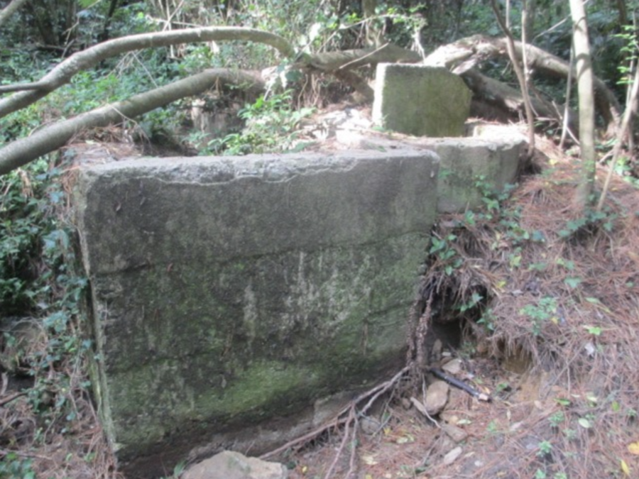
The septic tank below Selby St that was included in this scheme, is still there, 9M x 2M x 0.7M. It held 12,000 litres. There were complaints of it overflowing during busy periods in Katoomba and polluting the waterfalls.


The solving of the Flying Fox Gap photo mystery
Many years ago, I came across this photo (Fig C) from the BMHS ‘P683 Flying Fox Gap’ attributed to Harry Phillips. Naturally, I assumed that the title referred to the ropeway that went to the Ruined Castle as I knew of no other flying foxes in the vicinity. How wrong I was.

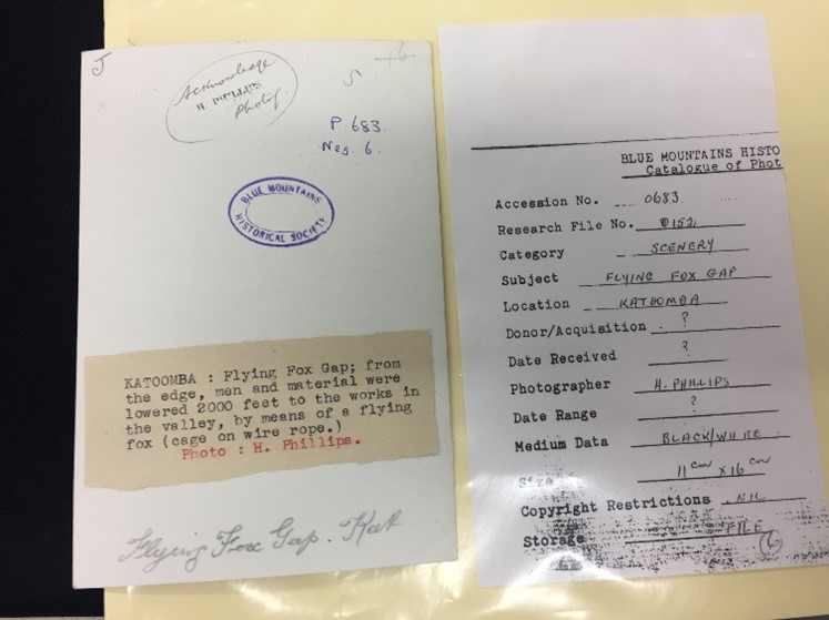
It showed a man leaning on a derrick with a cloth capped man in the background, and two men operating a windlass in the right background. Halfway down the cliff, on the rope leading down from the tip of the derrick was a long length of “something”, and on the ground next to the windlass was more unidentifiable equipment. In amongst the trees in the valley can be seen the remains of buildings. Harry Phillips used this photo with a few embellishments for the cover of a Tourist guidebook. I had no idea what the subject of the photo might have been, the only clue being the regrowth of the trees in the valley, around the miner’s huts, suggesting early 20th century.
Mr Fitzgerald took an almost identical photo. Fig 1.4.

The same derrick, the same length of what we now know is pipe hanging from the derrick. So now we can date the photo to 1909 or 1910 while the Katoomba Filter beds were being built.
THE KATOOMBA FILTER BED.
There are two more photos of the derrick and windlass. Fig 1.5 and Fig 1.6.


In the Fig 1.5 a Tee for the filter bed is being lowered, a vital piece of equipment, and Fig 1.6 shows the unmistakable background of the Three Sisters, with lengths of pipe, with the spray sockets already fitted, for the filter bed lying on the ground and a gate valve on the right.
This derrick lowered the equipment to the top of the flying fox which then carried it all the way to the filter bed site in one span. See photos Fig 1.7 and Fig 1.8.
The next two photos Figs 1.7 and 1.8 are taken from what today, is half-way down the Scenic Railway incline, one looking up and one looking down.
Fig 1.8: Daylight can be seen through the tunnel [red arrow] and the collapsed timbers that once supported the mine trackwork below the tunnel [yellow arrow]. The windlass working the flying fox is the [orange arrow] and the flying fox track rope is the [green arrow]. The derrick is the red circle. The dark blue arrow is the rope coming down from the derrick.
The upper end of the track rope is probably attached to one of the large iron rings that North had embedded in the rock wall to hold his trackwork from sliding down the hill.
Fig 1.7: Red arrow, a load descends the flying fox. Orange arrow, the bottom end of the track rope was probably anchored to the bolts that once held the diversion sheaves for the tramway, today still visible beside the miner’s hut on the boardwalk. The green arrow shows the small hut for storing equipment, the brick floor for this hut is still visible today. Red circle is the filter bed being prepared.
I was very excited to find these two photographs, as we have had no record of the incline in the period from 1895 to 1928.
The Windlass.
The shaft of the windlass is about 10” or 250mm in diameter. This gives a circumference of about 30” or 750mm. The crank handle radius is about 24” or 600mm. This gives a mechanical advantage of 4.8 to 1.
A 5’ length of 6” cast iron pipe weighs approximately 85 pounds, so the pull on the handle of the crank is 18 pounds. As the bulk of the work is lowering loads, the men are absorbing the thrust as the handle comes over the top of the turn towards them. The drop down the cliff is approximately 80 feet, so about 32 turns of the windlass are needed. The further down you go the heavier the rope becomes, 80 feet of ½” wire rope weighs about 30 pounds. As you can see the rope has climbed up on itself when it was being wound up, this is quicker when you are winding up the empty cable but makes it harder when lowering. But these are “real men who don’t eat quiche”.
The two long loose bolts poking through the uprights, are for the handle to jam against when they have stopped at the bottom, otherwise the weight of rope would unwind the windlass.
There is no brake, if the load got away there would be no stopping it, the handles would become instant decapitators.
The second flying fox was approx. 180M in length, needing 240 turns of the windlass, although not as heavy a load as it is a gentle slope, which one would you rather be working on?
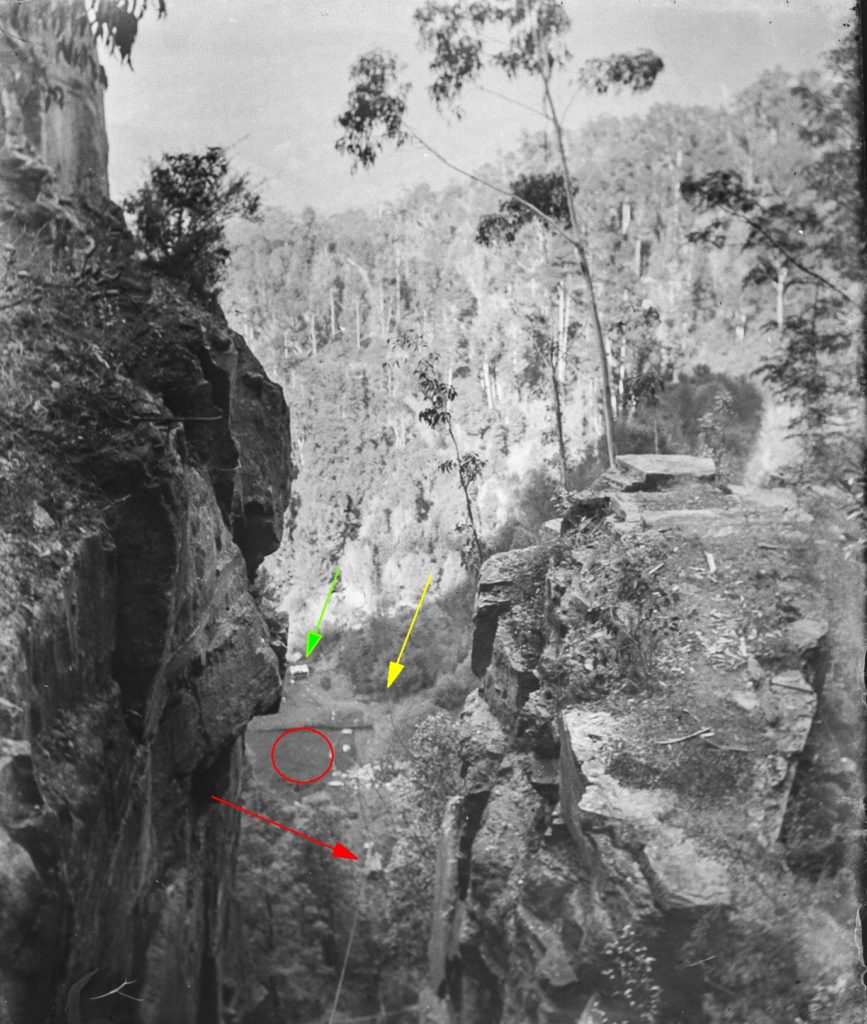


Fig 1.9 Brian Fox and his party explored that area on the Eastern side of the gully on Mon 1st June 2020 and discovered the carving. I propose that it was directions for workers engaged on pipeline and filter bed installation in 1910. The steps date from the mining era 1882-1903, the daily climb to and from work if you weren’t lucky enough to live in a humpy in the valley. This path/steps came down the gap between Orphan Rock and the rock column on the RHS of Fig 1.8, crossed to the West of the incline rail track just below where Mr. Fitzgerald is standing and on down to the mine.
THE KATOOMBA FILTER BED.
Fig 1.10: The Filter bed is being prepared. The red arrow shows where Echo Point is today.

A large amount of broken rock is used as the filter medium, and it was sourced from the immediate vicinity. Large rocks that appear in the 1890 photographs of the area by Kerry, Fig 1.11 and that should still be there today, are gone, broken up for the filter bed.

Figures 1.12 and 1.13 show the filter bed operating, with the unmistakable outline of the cliffs near Echo Point in the background. The gate valves from the previous photo 1.16 are now in use.
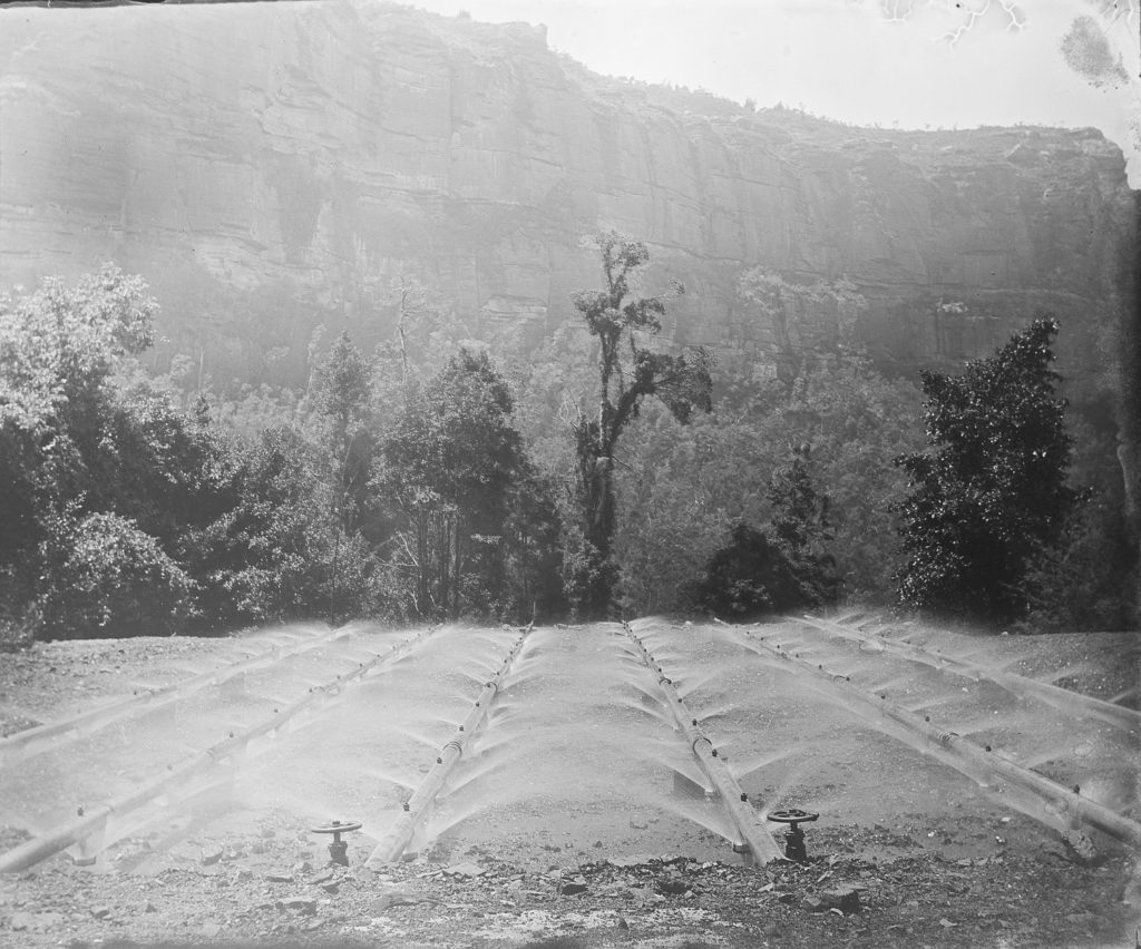


Fig 1.14 – This is the photograph posted by Jeff Brown 14th Feb. 2020 to the Facebook site “Do you Remember Katoomba When”, hand tinted. The corrugated iron shed in the right background was used to store lime and tools for maintaining the filter bed.The footings of that shed as well as the pipes are still visible today on the boardwalk at Scenic World.
Katoomba Filter Bed was an earlier design than the Leura beds, using a lighter filter medium and not having the secondary filtration.
Katoomba Colliery Ltd Fig 1.15, was registered on 29th May 1925, so the colliery and the filter beds operated together until 1935 when the sewerage diversion tunnel to Leura was installed, and this filter bed was abandoned.

Continue in Chapter Two – The Leura Filter beds, some more spectacular flying foxes.